3-9
183574-1CD
183574-1CD
3
Installation
3.4 Installing the System Components
ArcWorld 50/50S/52/52S
3.4 Installing the System Components
1. Inspect cell, fence, Robot, torch, and associated components for
shipping damage.
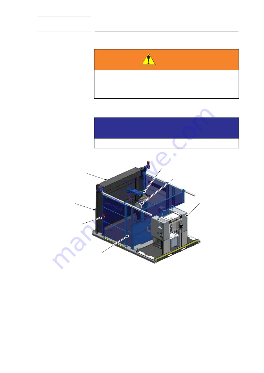
Fig. 3
-
5: Cell Assembly
2. Place the cell assembly base and Controller base according to the
system prints.
3. Attach all cables as shown in the system diagram.
4. Once components are correctly installed, anchor each component
securely in place (refer to the
Motoman Lagging Supplement
for
suggestions).
WARNING
• Make sure handling equipment can lift 340 kg (750 lbs),
approximate weight of the Controller Base Assembly.
Injury to personnel and damage to equipment can occur if rating of
handling equipment is not at least 340 kg (750 lbs).
NOTICE
Notify the shipper immediately if there is any equipment damage.
ROBOT
INTERLOCKED
WORK-CELL
ACCESS DOOR
CONTROLLER
BASE
ASSEMBLY
BARRIER DOOR
SAFETY FENCING
OPERATOR
STATION
POSITIONER
73 of 126


