background image

Summary of Contents for CACR-HR BAB Series

Page 1: ...DRIVES HR SERIES DESCRIPTIVE MANUAL FOR MULTI FUNCTIONS POSITIONING CONTROL SERVOMOTOR M F G D S R P SERIES SERVOPACK CACR H Ri_ii_i BAD RACK MOUNTED TYPE CACR HRI_ji_iBB BASE MOUNTED TYPE V YASKAWA TSE S800 6H ...

Page 2: ...9 266 _8995 AC Servomotors Servopacks Mli Base mounted Type I 390 37 General Precautions Some drawings in this manual are shown with the protective cover or shields I qg removed in order to describe the detail with more clarity Make sure all covers and shields are replaced before operating this product Some drawings in this manual are shown as typical example and may differ from the shipped produc...

Page 3: ...escribed in _ CAUTION may also result in a serious accident In either case follow these important items WARNING WIRING Grounding must be in accordance with the national code and consistent with sound local practices Failure to observe this warning may lead to electric shock or fire OPERATION Never touch any rotating motor parts during operation Failure to observe this warning may result in persona...

Page 4: ...SERVOMOTOR only in test run ql without load Failure to observe this caution may result in personal injury Before starting operation with a load connected make sure emergency stop procedures are in place Failure to observe this caution may result in personal injury During operation do not touch the heat sink regenerative resistance SERVOMOTOR and other peripheral devices il Failure to observe this ...

Page 5: ...CATIONS OFAC SERVOPACK 44 _C_ONNECTION 55 _6 I 0 SIGNAL OPERATION AND FUNCTIONS 95 SERIALCOMMUNICATION 121 _8 PARAMETERS 145 DISPLAY SETTING MONITOR FUNCTIONS 182 _0 INSTAL_TION AND WIRING 197 1 TEST RUN MAINTENANCE AND INSPECTION 201 _2 PERIPHERALDEVICES 223 3 DIMENSIONS 250 D _4 APPENDIX PARAMETER SETTING 278 m 3 D ...

Page 6: ...2 Allowable Radial Load and Thrust Load 34 FOR I O SIGNAL 70 3 2 3 Mechanical Specifications 35 5 5 1 Applicable Receptacle 70 3 2 4 Rotating Direction 35 5 5 2 Connector 4CN Layout and Connection 70 3 2 5 Shock Resistance 35 5 5 3 Description and Usage of I O Signals of Connector 4CN 72 3 2 6 Vibration Resistance 35 5 6 CONNECTOR TERMINAL 5CN 3 2 7 Vibration Class 35 FOR I O SIGNAL 73 Jml 3 3 REC...

Page 7: ... 5 TROUBLESHOOTING GUIDE 217 SERVOPACK RESPONSE 125 11 5 1 AC Servomotor 217 7 6 SERIAL COMMUNICATION CONTROL CODE 125 11 5 2 Servopack 218 7 7 AUTOMATIC TRANSMISSION DATA FROM SERVOPACK 126 12 PERIPHERALDEVICES 223 7 8 SERIAL COMMAND 129 12 1 COMBINATION OF PERIPHERAL DEVICES 223 7 8 1 Serial Command List 129 12 2 BRAKE POWER SUPPLY 227 7 8 2 Command Functions 130 12 3 BRAKING RESISTOR UNIT TYPE ...

Page 8: ... Radial Load and Thrust Load 3 2 2 34 CONNECTION 5 55 APPENDIX PARAMETER SETTING 14 278 Connector 2CN Layout and Connection t5 3 2 62 Applicable Receptacle Specifications 5 3 1 61 Connector 3CN Layout and Connection 5 4 2 67 Applicable Receptacle and Connector 4CN Layout and Connection 5 5 2 70 Cable Specifications 5 4 1 65 Connector 5CN Layout and Connection 5 6 2 73 Applicable Receptacle 5 5 1 7...

Page 9: ...22 OF 5CN INPUT SIGNAL 6 2 101 OPERATION AND FUNCTIONS _ OF 2CN 5CN OUTPUT SIGNAL 6 3 114 Operation Check 11 2 2 209 High Voltage Line 4 4 4 53 ORDER ELECTRICAL DEVICES 14 2 278 How to Use 12 9 3 243 OUTLINE 1 9 How to Use Axis Address 7 3 2 123 Output Circuit Refer to Figs 5 7 5 14 and 5 15 6 3 1 114 Overhanging Load 4 4 1 52 I O SIGNAL OPERATION AND FUNCTIONS 6 95 irl Input Circuit PARAMETER CHE...

Page 10: ...TINGS AND SPECIFICATIONS OF TEST RUN MAINTENANCE AC SERVOPACK 4 44 AND INSPECTION 11 201 RATINGS AND SPECIFICATIONS 4 1 44 Test run Preparations 11 2 1 203 RECEIVING 10 1 197 TEST RUN PROCEDURES 11 2 202 RECEPTACLES 3 3 36 TRANSMISSION DATA SERVOPACK _ HOST CONTROLLE R 7 4 124 Rotating Direction 3 2 4 35 Transmission Method 7 3 1 122 R Series For 100V 3 1 7 30 TROUBLESHOOTING GUIDE 11 5 217 R Seri...

Page 11: ...ndexing points station numbers are input as I position data Speed data are selected from four types of speed set in the Servopack by parameters by speed selection signals Both one way rotation and short cut rotation are possible Range of station numbers Binary coded decimal BCD 0 to 999 Binary 0 to 4095 Digital Switch DG SW Positioning data are input by contacts from digital switches relays I Thum...

Page 12: ...Zero point Used for zero point return homing when incremental encoder is used Return Homing Mode Two types of methods can be selected 1 Decel limit switch and encoder C pulse signal are used 2 Only stop limit switch is used I Software Revised Version I Some functions of the CACR HR type have been added with the revised software Concerning the additional functions in Table 1 3 check the software ve...

Page 13: ...sition Figs 1 and 1 2 show the software yersion indications sorrwA_ VEaSIO N SERVOPACK CACR HR f_J i CN 0 I Fig 1 1 Software Version Indication of HR _ _ BAB IC42 _ SOFTWARE i LED3 Fig 1 2 Software Version Indication of HR _ _ BB 11 ...

Page 14: ...ENCODER M Rare Earth S 8192 pulses rev Absolute MOTOR OOTPUT W 1024 pulses rev Absolute Refer to Par 2 2 2 8192 pulses rev Incremental DESIGN REVISION OR _ _ 1 3 2048 pulses rev Incremental A B C 4 2500 pulses rev Incremental 2 Servopack CACR HR 05 B A B 1 2 J I I ACSERVOPACK SERIES POWER SUPPLY VOLTAGE Provided only for Single Phase CONTROL TYPE I Power SupplyVoltagelOOV Multi function 2 Power Su...

Page 15: ... 37ES to 0903 USASEM O2AS G t3A3 S to to 30AS 44A3 USAREM A5CS 2OOV USADED OSE3 R to D to 07CS 37E3 USAREM A5DS IOOV to USASEM O2A3 05DS S to 30A3 Absolute USAMED O3BW M to Incremental USAMED O3B2 1024P R 60BW M to 8192P R 60B2 USAFED O2CW F to USAFED O2D2 44CW 03D2 F 05C2 USAGED O2AW to G to 44C2 44AW USADED O5EW USAGED 02C2 03C2 D i to G 05A2 37EW to I i USASEM O2AW 44A2 to USADED O5E2 30AW D to...

Page 16: ...67 5 121 5 183 5 I GD2d4 lb in S 2x 10 a 5 75 9 60 107 5 162 5 Type USAGED 02 _ _ I 03 _ I 05 _ i 09 _ _ i 13A _ 2 Applicable kW 0 15 0 3 0 45 0 85 1 3 Servomotor Output 8P 0 2 0 4 O 6 I I 1 7 1_ I Speed r min Rating 1500 Max 3000 Rating t500 Max 3000 _ Continuous Output Current Arms 3 0 3 0 3 8 7 6 11 7 Max Ontpnt Current Arms 8 5 8 5 11 0 IT 0 28 0 Allowable Load Inertia kg cm 6 5 10 3 67 5 121 ...

Page 17: ...ng 3000 Max 4500 Continuous Output Current Arms l O 2 0 2 7 3 6 5 7 Max Output Current Arms 2 8 5 7 7 8 10 6 16 3 Allowable Load Inertia kR cm 2 _ 1 95 3 2 4 9 23 9 32 85 JL GD L 4 OZ in S x 10 _ 27 75 45 15 69 5 339 465 Table 2 2 Rack mounted TypeServopack Single phase IOOVAC Configuration Main Circuit Voltage Rack mounted Type Single phase IOOVAC Type CACR HR A5BABII OIBABII 02BABII 03BABII 05BA...

Page 18: ... 5 75 9 60 107 5 162 5 256 486 633 5 m Type USAGED 02 _ _ 1 03 _ _ 1 05 _ _ 1 00 _ _ 1 13A _ 2 20A _ 2 30A _ 2 44A _ 2 Applicable kW 0 15 0 3 0 45 0 85 1 3 1 8 2 9 4 4 Servomotor Output HP 0 2 0 4 0 6 1 1 t 7 2 4 3 9 5 9 Speed r min Rating 1500 Max 3000 Am II _ ContinuousOutput Current Arms 3 0 3 0 3 8 7 6 11 7 19 0 26 0 33 0 Max Output Current Arms 8 5 8 5 11 0 17 0 28 0 42 0 56 5 70 0 Allowable ...

Page 19: ...chment ISERVOMOTOR _ RECEPTACLES CON NECTORS b ii 6 589 589 n5 7 I See Par 3 3 AC SERVOMOTOR SERVOPACK See Pars 5 3 to 5 6 HR SERIES Option Option PARAMETER I I EXTERNAL POSITION INDICATOR DIGITAL SWITCH UNIT 589 37 See par 12 8 J CONTACT INPUT UNIT MANUAL PULSE GENERATOR CONNECTION CABLE UNIT 588 327 591 I0 See Yaskawa Controls Co Ltd Catalog HSE CO 16 17 ...

Page 20: ...of M Series AC Servomotors _otor Type USAMED OSAMKD Item _ _ 03_ _ lI06E E llOOB 2 12BIll 2 20B 21308 _ 2 44B _ 2 60B 2 kW 0 3 I 0 6 0 9 1 2 2 0 3 0 4 4 6 0 Rated Output RP 0 4 I 0 8 1 2 1 6 2 7 4 0 5 9 8 0 N m 2 84 5 68 8 62 11 5 19 1 28 4 41 9 57 2 RatedTorque lb in 25 50 76 102 169 252 372 507 N m 8 82 11 8 21 6 62 9 Continuous Max Torque _b in 2 94 I 5 88 32 3 46 1 26 I 52 78 104 191 286 408 5...

Page 21: ...150c i 1500 _ SPEED A _ B SPEED r min 100C J r rain A_ B 1000 500 500 _ I _ 12 16 N m 0 10 20 I 30 N m _ 50 100 150 2 0 Ib in _ 1001 200 3 _0 Ib in RMS TORQUE RMS TORQUE USAMED 20B USAMED 30B 2 _ m _ _ _ 2 c _i_ _ 150 150c SPEED A _ B SPEED _ _ r min I OOI r min A B t oooI N m C iN m 20 3 0 0 b i 366 100 200 C 150 300 450 6_ 0 Ib in RMS TORQUE RMS TORQUE USAMED 44B USAMKD 60B 2000 2000 SPEED SPEED...

Page 22: ...s AC Servomotors Item 02 1 03_2 2 1 05 Jill 1 09 _i 1 1 113C _52 20C 2 30C 5_ 2 44C _ 2 kW 0 15 0 3 0 45 0 85 1 3 1 8 2 9 4 4 Rated Output HP 0 2 0 4 0 6 I 1 1 I 1 7 2 4 3 9 5 9 N m 0 98 1 96 2 84 I 5 39 I 8 34 11 5 18 6 28 4 RatedTorque lb in 8 7 17 25 I 48 I 74 102 165 252 Continuous Max N m 1 08 2 16 2 94 I 5 88 I 8 83 11 8 22 6 37 3 Torque lb in 10 19 26 I 52 78 104 200 330 m Instantaneous N m...

Page 23: ...0 2000 _ t _ t _ i _b _ SPEED 1500 _ I SPEED _5 i l r min 1 A B 1000 000 500 I1i li IiIJ L L I _ _U 6 8 10 N m O I 51 101 15 l N m i _ 2_ 4 i i _0 50 100 150 b in 0 20 40 60 _ 87 Ib in i I I RI IS TORQUE J_ C RMSI ORQUE _ i _ _ _ 25oolZZ_ 2_6o _t i b_ _ u SPEED I II 5 n rim n I AIII B III I r re n A I B _ U 5 10 151 20 125 I N m 10 20 30 40 I N m _ _ 6 50 150 150 200 250 Ib in 0 100 200 300 400 Ib...

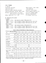
Page 24: ...pulses rev USAGED X1 A 2 X1 With incremental encoder 8192 pulses rev 05 to 44 USACED X 1 C 2 1 With incremental encoder 8192 pulses rev 02 03 l Semi Standard USAGED X1 AW 1 With absolute encoder 1024 pulses rev USACED 3 3 A 3 1 With incremental encoder 2048 pulses rev 13 to 44 USAGED I 3 C3 K1 With incremental encoder 2048 pulses rev 02 to 09 Table 3 3 Ratings and Specifications of G Series AC Ser...

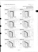
Page 25: ...AGED 09 j r I I I I I I 1 SPEED rlmin I I I I 0 30 60 s o Ib4n RMS TORQUE SPEED rlmin l fl 3000 2000 1000 0 5 10 15 N 1 rli I I I 0 50 100 1 5 0 Ib4n RMS TOROUE USAGED 13A USAGED POA SPEED O 2000 SPEED rlmin r min 1000 1000 0 10 20 30 0 1 I I P4 m L I I N 4 0 loo 200 300 lb in 0 loo 200 300 IbGn RMS TORQUE RMS TORQUE USAGEDz30A USAGEDzMA 3000 3000 2000 SPEED 2000 SPEED rlmin rlmin 1000 1000 0 20 4...

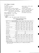
Page 26: ...omotors __ueu 05E _ 10E_i 15_ _i 22E 7_ 37E _ Item kW 0 5 1 0 1 5 2 2 3 7 9 Rated Output BP 0 67 1 3 2 0 2 9 5 0 N m 2 35 4 81 7 16 10 5 17 7 Rated Torque lb in 21 43 63 93 156 N m 3 43 6 37 8 83 13 7 21 6 Continuous Max Torque lb in 30 56 78 122 191 Instantaneous N m 8 24 16 9 25 1 36 8 61 8 Peak Torque lb in 73 149 222 326 547 Jl II Rated Current A 3 5 7 9 12 6 16 6 23 3 Rated Speed r min 2000 I...

Page 27: ...in A B 1ooo 1ooo 500 50 0 2 5 5 7 5 iN m 0 IN m 2 s _o _ Ib i 6 _o i_o i_o Ib in RMS TORQUE RMS TORQUE USADED 15E USADED 22E DO3 oo 2ooo 2ooo I SPEED 150G SPEED 150GI rlmin A i B rlmin 1000 A I B 1ooo i I 1 500 I so l 13 8 16 124 32 N m iN m _ I_ 0 200 3_ 0 Ib in 0 100 200 300 400 Ib in I RMS TORQUE RMS TORQUE USADED 37E 2 5OC 2ooc _ _ Jl SPEED 15oc A r min 100C _ B 5oc N m 20 200 400 600 Ib in RM...

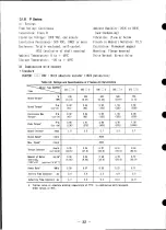
Page 28: ...cations orS Series AC Servomotors _otor Type USASEM 02A 2 03A 2 05A _ 2 i OSA i 1 15A 1 30A i Item _ _ I W 154 I 308 462 771 1540 3080 Rated Output HP 0 2 I 0 4 0 6 1 0 2 1 4 1 i N m 0 49 I 0 98 1 47 2 45 4 90 9 81 Rated Torque lb in 4 3 J 8 7 13 22 43 87 i N m 0 57 I 1 18 1 67 3 33 6 18 12 2 Continuous Max Torque lb in 5 0 I 10 15 30 55 108 i N m 1 47 J 2 94 4 02 7 35 13 7 29 0 Instantaneous Peak...

Page 29: ...1 5 2b Ib in 0 1 0 2Jo 30 410 Ib in RMS TORQUE RMS TORQUE USASEM 05A USASEM 08A ooo r 3000 3000 SPEED SPEED r Tin 200C A B r Tin 2000 B ooo _ _ _oo _ 0 1 2 3 4 5 N m 2 4 6 8 N m 4 o 2 o _o o 5 0 Ib in _ 2 o _ o do 8 o0b in RMS TORQUE RMS TORQUE USASEM 15A USASEM 30A o___ oo __ _ _ 3OOC 3OOC SPEED SPEED A B r Tin A B r Tin 2OOC I I 200 1ooc I I ooc 0 5 10 N m C N m b 50 I_ 0 15_ Ib in 6 I I Ib in l...

Page 30: ...i 2 Item _ W 50 I00 200 300 500 700 Rated Output HP 0 07 i 0 13 0 27 0 40 0 67 0 93 I N m 0 159 0 318 0 637 0 955 1 59 2 22 Rated Torque oz in 22 5 i 45 90 135 225 316 all N m 0 19 0 382 0 765 1 15 1 90 2 67 l Continuous Max Torque oz in 26 9 54 2 108 3 162 5 269 4 378 l N m 0 476 I 0 955 1 91 2 86 4 76 6 68 Peak Torque oz in 67 5 135 270 405 675 948 Rated Current A 0 71 1 0 2 0 2 7 3 6 5 7 Rated ...

Page 31: ...SAREM _01C 3000 3000 _ SPEED e SPEED A B r min 2000 r min 2000 0 2 o 4 o 6 N m 0 0 2 0 4 0 6 0 8 1 0 IN m I i i 25 _o 7 5 oo ioz _ l _ _ _o 1_o oz _o RMS TORQUE RMS TORQUE USAREM 02C USAREM 03C 3000 3000 I 11 A B r min A B SPEED 2oo6 _ 20c r min 1 1000 1000 0 0 4 0 8 1 2 1 6 2 0 N m 0 0 6 1 2 1 8 2 4 3 0 IN m 1_o 2_ _ ioz _ _ 11o 3_o 41oioz _ _ RMSTORQUE RMSTORQUE USAREM 05C USAREM 07C 300G 3OOO S...

Page 32: ...M I Item _ A5Dr 2 OlD _ 2 02D 2 03D 2 05D _ 2 W 50 100 200 300 500 Rated Output HP 0 07 0 13 0 27 0 40 0 67 N m 0 159 0 318 0 637 0 955 1 59 Rated Torque oz in 22 5 45 90 135 225 41 Continuous Max N m 0 19 0 382 0 765 1 15 1 90 Torque oz in 26 9 54 2 108 3 162 5 269 4 N m 0 476 0 955 1 91 2 86 4 76 Peak Torque oz in 67 5 135 270 405 675 Rated Current A 1 2 1 7 2 9 3 6 5 5 Rated Speed r min 3000 Ma...

Page 33: ...le variation range USAREM A5D USAREM OID At B SPEED SPEED 2OOG A B i r rain t r min pop 1 ooo 0 0 2 0 4 0 6 N m 0 0 2 0 4 06 0 8 1 0 N m I I 0 25 50 75 100 oz in _ 5_ 1_0 150 oz in RMS TORQUE RMS TORQUE USAREM 02D USAREM O3D 4000 i__ _ _ 4000 3o0o _ l 3ooo AI B _ SPEED 2o00 _ _i _ SPEED A B 1 1 r min I i r rain 2000 looo looo 0 0 4 0 8 1 2 1 6 2 0 N m 0 0 6 1 2 1 8 2 4 30 N m _ I_ 0 200 3 S0 oz in...

Page 34: ... 2 02C _ 2 03C _ 2 05C _ 2 07C _ 2 Item W 100 200 300 500 750 Rated Output HP 0 13 0 27 0 40 0 67 1 0 N m 0 32 0 64 0 95 1 59 2 39 Rated Torque oz in 45 90 135 225 339 Continuous Max N m 0 32 0 64 0 95 1 59 2 39 _ Torque oz in 45 90 135 225 339 1 N m 0 96 1 91 2 86 4 76 7 06 Peak Torque oz in 136 270 405 675 1000 Rated Current Arms 1 0 2 0 2 7 3 3 5 7 I Rated Speed r min 3000 Max Speed r min 4500 ...

Page 35: ...ristics may be reduced even f the values are with in the allowable variation range Type USAPEM 01C Type USAPEM 02C 4000 _ 3 _ _ _ 4OOO _ _ _ 3O0O sPEEDs i S EED A B rlmin 20 X_ i r min 2000 0 0 25 0 5 0 75 N m 0 0 5 1 1 5 2 N m RMS TORQUE MS TO DUE Type USAPEM 03C Type USAPEM 05C I I SPEED A It B SPEED A r rain 2ooc I r min I tl 0 0 75 1 5 2 25 3 N m 0 1 5 3 4 5 6 N m RMS TORQUE MS TO QUE Type USA...

Page 36: ...AIlowable kl Iowable 03A _ Motor Type Ra dial Load Thrust Load 245 55 98 22 USAFED N lb N lb 05A 02 _ I 08A 392 88 147 33 49 11 t 147 33 03E_ _iI 15A _ 490 110 05_ 1 490 110 98 22 t 30A 686 154 196 44 09 _ _ 1 R Series 13C 2 686 154 343 Allowable AIlowable Motor Type Radial Load Thrust Load 2OC 2 USAREM N lb NOb 30C 2 1470 331 490 110 A5 _ _ 2 78 4 18 39 2 9 44C _ 2 Ol f _r _ L 2 G Series o2 _ L 2...

Page 37: ...ng 0 Fig 3 11 3 2 5 Shock Resistance Whenmounted horizontally and exposed to vertical shock impulses the motor can withstand up to two incidents with shock acceleration of 490 m s2 5OG Fig 3 12 Note A precision detector is mounted on the opposite drive end of AC servomotor Care should be taken to protect the shaft from impacts that could damagethe detector 3 2 6 Vibration Resistance When mounted h...

Page 38: ...e USAMKD 6OBETi2 Type USASEM O3A to 30A D E Alarm terminal F PhaseW Frame Ground Fan motor connection I 1 Power supply single phase I___f__q__j s Alarm contact HADING OFF at fan rotation normal COIL ONat 1800 200r min or less ON for 3 seconds after starting Contact capacity Resistance load max ll0V 0 3A b Detector receptacle Incremental encoder G A ChannelAoutput K B Channel A output L C ChannelB ...

Page 39: ...tor side 4 PIN TYPE PC2005 M iUSER PIN TYPE PC2005 F 350 50 13 78 1 97 _ 25 L _ Phase 1J Red Phase V White PhaseW Blue FrameGround Green AWG 20 4C b Detector side absolute encoder 350 50 13 78 1 97 __ 35 1 CAP TYPE172163 1 _ SOCKET TYPE170365 1 PLUG TYPEI72171 1 CABLE KQVV SW PIN TYPE170363 1 AWG22 x 3C AWG26 x 6P 1 Channel A output Blue 9 Frameground Green Yellow 2 Channel Koutput White Blue 10 C...

Page 40: ...AREM 02C 02D 03C 03D q Color of Lead Applicable Red Phase U _ A Phase U White Phase V _ B Phase V Blue Phase W C Phase W Black Brake D E Braketerminal Black Brake F Frame Ground Green Frame Ground USAREM A5C A5D OlC OID q USASBM 08A to 30A USAREM 05C 05D 07C _ A Phase U B Phase V h Phase U C Phase W B Phase V O E Braketerminal C Phase W F Frame Ground D B Brake terminal F FrameGround _ 1 P Series ...

Page 41: ... 39 ...

Page 42: ...cle L type Straight Cable Receptacle L type Straight Cable USAFED Plug Plug Clamp Plug Plug Clamp 02 _ _ 1 MS3102A MS3108B MS3IO6B MS3057 MS3102A 14S 2P 14S 2S 14S 2S 6A 14S 29P 03 l MS3IO2A MS3108B MS3106B MS3057 MS3102A 09 _ _ I 18 10P 18 10S 18 IOS IOA 20 29P MS3IO8B MS3106B MS3057 20 295 20 29S 12A 13C 2 20C 2 MS3102A MS3IO8B MS3106B MS3057 MS3102A 30C 2 22 22P 22 22S 22 22S 12A 20 29P Jl 44C ...

Page 43: ...6S 14S 6S 6A MS3102A MS3108B MS3106B MS3057 20 15P 20 t5S 20 15S 12A MS3102A MS3108B MS3106B MS3057 Note Theseconnectors 24 IOP 24 IOS 24 t0S t6A aremade by DAI ICHI DENSHI KOGYO Co Ltd Holding Brake Receptacle L type Plug Straight Cable Clamp Plug MS3102A MS3IO8B MS3106B MS3057 14S 6P 14S 6S 14S 6S 6A MS3102A MS3108B MS3106B MS3057 20 15P 20 15S 20 15S 12A Notes D I For connection parts p ugs cla...

Page 44: ... 20 4S 12A 30A _ Note There connectors madeby DAI ICHI DENSHI KOGYO CO LTD Table 3 16 R Series Characteristics of AC Servomotor Detector and Holding Brake Option for Standard Combination AC AC Servomotor Detector i Holding Brake Servomotor Type Receptacle L type Cable Receptacle L type Cable Receptacle L type Cable USAREM Type Plug Clamp Type Plug Clamp Type Plug Clamp _I A5C 2 MS31OIA MS3106B MS3...

Page 45: ...ake for StandardCombination AC Servomotor Detector HoldingBrake AC Servomotor Type Connector MATE N LOCK USAPEM Pin Terminal Conversal Pin Terminal Plug Pin O1C 2 PC2OO5 M 172171 I 170363 I PC2OO5 M 02C 2 PC2OO5 M 172171 I 170363 I PC2OO5 M 03C 2 PC2OO5 M 172171 I 170363 I PC2OO5 M O5C 2 PC2OO5 M 172171 I 170363 I PC2OO5 M Note The typeof connectors O7C 2 PC2OO5 M 172171 1 170363 1 PC2OO5 M prepar...

Page 46: ...No and speed No command coo act data Method Command Input Position command Sign t up 1o 8 digits 99999999 to 190999999 Speedcommand Up to 6 digits OOO000 to 240000 to be less than motor max speed Position speed No command BIN up to 6 bits 1 to 641 System Only absolute value commandavailaMe Others Operation Spec Positioning by pulse train line PGor pulse train input Command Input Position command N...

Page 47: ... to 64 Only absolute value command available Positioning by pulse train line PGor pulse train input Position command Numberof pulses A t B or UP DNor P t SIGN Speedcommand Up to 400 kpps A B 1 6 Mpps Only incremental command available Operated at main powerOFF servo alarm servo OFF Output signal for turning brake powersuppty ON OFF brake timing is set by parameter 01 to 05 built in regene Built in...

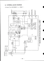
Page 48: ...4 2 INTERNAL BLOCK DIAGRAM Servopack Type CACR HRA5BAB 2 to 05BABE L 46 ...

Page 49: ... Servopack Type CACR HRIOBAB 15BAB 47 ...

Page 50: ... 48 ...

Page 51: ...ervoltage OV Excessively high DCvoltage in the main circuit approx 420V Overspeed OS Excessively large speed feedback detected Under Voltage or LowDCvoltage in the main circuit after power ON 150V or less Overload OL Overload condition of motor and Servopack Heatsink Overheat OH Overheat of heatsink approx 85 Cmin only for type HR_ BB PG Disconnection PG Encoder signa 1 disconnection Overflow Devi...

Page 52: ...at the maximum operating time at higher rotating speed is shorter for the same overload NOTE Overload detection level is determined with hot start conditions of ambient temperature 55 C The set value cannot be changed I000 I00 OPERATING N 0r rain TIME S AT MOTOR N 3000r min _ AT RATED 1 SPEED 1 0 7 100 2O0 3O0 MOTOR RATED CURRENT 4 Fig 4 4 Overload Characterisitics 50 ...

Page 53: ... signal turns off only themain circuit _ _ _ as shown in Figs 5 17 and 5 18 This allows rapid reaction ill the event of a malfunction If the power to the control circuit _ _ is simultaneously turned off this also turns off the LED in the Servopack indicating the cause of the alarm signal CAUTION When an alarm signal cuts off only the main circdit turn off servo ON_ SVON signal before supplying pow...

Page 54: ...etails contact your Yaskawa representative 9 4 4 3 Allowable Cyclic Operating Frequency Start Stop cyclic operating frequency is limited separately by Servopackand Servomotor it is necessary to satisfy both conditions 1 Allowable cyclic operating frequency limited by Servopack Servopack limitation is due to Servopack built in regenerative resistor generating dl power Allowable frequency differs de...

Page 55: ... voltage must be dropped from 400 440Vto 200 V by using a power transformer Table 5 13 shows the transformer selection Connection should be made so that the power is supplied and cut at the primary side of the transformer IOOV for Servopack type HR E iE BABll 53 ...

Page 56: ...5BAB 11 7 80 20 130 BRO3BB 3 0 20 I0 90 din HRO5BB 4 2 40 10 110 I HRIOBB 7 6 70 20 150 HR15BB 11 7 80 20 160 60 HR2OBB 18 8 100 40 200 BR3OBB 26 0 160 80 300 HR44BB 33 0 210 100 370 HR6OBB 45 0 300 120 480 HRA5BABI1 1 2 20 50 HRO1BABll 1 7 25 6 61 HRO2BAB11 2 9 40 6 30 76 HRO3BABll 3 6 50 6 86 HRO5BABll 5 5 45 15 90 Power loss In regenerative resistors occurs at motor deceleration The maximum all...

Page 57: ...ERVOTROUBLE INDICATION I POWER ON _ L _ _ _ _ POWER SUPPLY ON OFF o FRO ESUR ESUPR R I 1 MC SUP TO MAGNETIC CONTACTOR OR RELAY I FI 1 I 2 I MOTOR I tMC LJ MC_ZZ R S SERVOPACK PROVIDED YUSER If _ l Ry _ DO NOT FAIL FAN ALARM 2 v I __ LM TOCROUND 02 V ENCODE 1 SUPPLY j I _ 12 g_ 19 24v SERVOON _ 13 02 V DO NOT FAIL TO PROCESS CONNECTINGCABLES USEYASKAWADWG SHIELDED CABLE ENDS DP8409123 DE8400 FJ3 OR...

Page 58: ... OPERATION _ w _ MCCW 12 LII_ CA IP _ DC AVR ALARM RESET o _ RST 5 FEEDSPF_SEt ECr _ _ SP3RD 46 1 c FA _ _ _ DR Oov 132 3 _ 1_ FA _ P _ 9 I_rATING DIItECn0NSELECT _ DR T 14 11 FB _ PG PULSE OUTPUT ov F _3___a 0v l r i18 20 FG x I o o CDO 16 Note The wiring length of the external pulse train o _ Co T 17 reference setter must be 5m or less o o CD2 24 cm ias STATION NO REF DATA _ C _ 27 _BCDOR BINARY...

Page 59: ...OR LINEPGSWITCHING o _ MPG LPq _ _ 8 L_ 13 FA P 0V _ 0V 2 18 FB J PG PULSEOUTPUT i8 2t 0V __ t DSO_ _ _4 _ _I _ _ EXTERNALPOSITIONINDICATOR TYPEMCIF LS 3 0v _ _ I I I I_I I_VI IN 1 I DSO0 _ 20 J_f I _ i Note The wiring length of 18 1 DSII0 16 _L the line PG or pulse DSlll i__ L 7 train input and exter 5VDC mustbe 5mor less DSI13 _ 5 4CN USED ATPARAMETER SETTING DSIIS 27 t 14 TXD it l I _l_ _ XD Ie...

Page 60: ...nnection at Positioning by DG SW Data Cont d 1 21 20 19 Ill 1 II I IlL Illl Ill I iJJl 1 IJll I I IPOSITION REF 1 8 IIII I1 IIII I1 _o III1 i IIII II n II FEED SPEED REFERENCE DATA I Fig 5 4 Details in DG SW Unit q 58 ...

Page 61: ... OPERATION FWD ON EXT PULSE GENERATOR SKIP MANUAL OPERATION STOP ZRN ZER0 POINT RETURN START 20P 5VDIFFERENTIAL OUTPUT TYPEI PON EXT PULSE TRAIN 1_ CA _ t _ PA OPERATION MODE _ i CA tP _ __ DC AVR 1 _ _ CB IP 3 AUTO TRANSMISSION DATA FROM SERVOPACE COIN POSITIONINGCOMPLETE 0V f l ALMx ALARM ALARM NAME I I t 19 FA TYPICAL MONITOR DATA 1_ FB 1 _ PGPULSEOLITP T PUN x x CURRENT POSITION _P PER x x POS...

Page 62: ...IAL OUTPUTTYPE CW O O MCW l _ 7 CA ts_ _ PA MANUAL OPERATION Iccw _ MCCW 12 _ I CA PI I _PA _ XN _ De AVR CURRENT LIMIT COMMAND O _ CU R _ 0 CB l PRpFBn_ _ __ _ _ _ v ALARM RESET oo RST _ CB P _ SP2ND 0V FEEDSPEEDSELECT _ SPaRD l FA FB _ PG PULSEOUTPUT VB P_ ov _ _ ov OV _ i33 _ f 1 O O C_ tl6 21 FG J 2 0 8 CD i iT POSITIONNO 4 _ O o C _ 24 SPEEDNO C _ r i25 REFERENCEDATA 8 _ o 16 _ o o C _ 126 32...

Page 63: ...tor cooling fan Conection needed only when Type USAMKD 60B is rE3 r_ 6 qL_J connecting terminal used 1 _ _ for Type HR r _ BABI_ 2 Single phase 100 to ll5VAC 1096 50 60Hz for Type HR 7 BABll 15 10 6o z BABI2 Single phase 200 to 230MAC 15 50 60Hz for Type HR 3 C _ _ only for Type HR6OBB 10 o 50 60Hz for Type HR i i BABll 4 Single phase 100 to II5VAC 15 5 External resistor must be connected for Type...

Page 64: ...urn STP 24V Battery Input for Absolute Zero Point Encoder Stop LS Input 8 10 11 12 13 SVON N OT P OT ALM BK OV Overtravel LS Input Servo ON Input Servo Alarm Brake Release OVfor ALM Reverse Side Forward Side Output Command Output BKSignal STOP AS T PCON 24V FG Temporary Stop Start Command At Zero Point Proportional 24V for Input CommandInput Input Return Decel Operation Signal Shielding LS Input C...

Page 65: ... _ TEMPORARY I STOP I O _ SIDE _ P OT _ FORWARD m_ 7 ZERO_POINT RETURt DEC _ _ HOMING _ __ j DrCEL CS _ O O PEON l _ PROPORTIONAL OPERATION 2 2 4 TkQ _IHOMINGI STP _ 1 _ _ I DECEL LS t _j 1 RY ALM 2 11 r 1 2 RY B K 2 12 r I 2 13 _ L__ _ BRAKE RELEASE 2 20 Fig 5 7 Wiring Diagramfor 2CN 63 ...

Page 66: ...d side Com ects overtravel limit switch signal overtravel LS r according to forward or reverse side This signal is turned on at normal P OT i0 Reverse side operation and off when limit switch overtravel LS is active DEC 17 Zero point Used in zero point return homing mode I return homing r_ i refer to Par 6 2 3 I d After decel LS 2 step deceleration by DECsignal and phase C pulse signal zero point ...

Page 67: ...ons D Table 5 4 Applicable Receptacle and Cable Specifications Specifications Applicable Receptacle Type Connecting Cable of Connector Used Specifications in Servopack SolderedType CaulkingType Case Maker MR 2ORIL_ HONDA DP8409123 Right angle 20P MR 2OF MRP 2OF01 MR 20L Tsushin B9400064 or D Co Ltd DE8400093 Standard attachment Of Servopack Note For connecting cables YASKAWA supply the cables with...

Page 68: ...te Internal blue blue Configuration and I 5lPurple white Twisted Lead Colors B2 Yellow white _ Yellow white cable DP8409123 yellow yellow Twisted 6lBlue brown and cable B9400064 Bs Green white F_lPale green 71Yellow brown are standard green Twisted white pale cable green 8 Green brown B4 Orange white orange F Orange white 91Red brown orange B5 Purple white lOJPurple brown purple B8 Gray white gray...

Page 69: ...ayout I I Pc v PGOV PCOV PG_V Pc_v P_V BAT _ BAT0t Required only whenabsolute encoder is used 0 2nun ABSOLUTE ENCODER 3 CN SERVOPACK BLUE PA D PA 3 17 PB PB 3 19 PC PC 15 5VP VP I1 3 3 10 t 12 13 20 CABLE DP8409123 1_33 lifif_c __0_9 P Receptacle __ Accessory not attached Note _ shows twisted shielded cable Type MS3108B20 29S Angle plug Type MS3057 12A Cable clamp s Fig 5 8 Connection between 3CN ...

Page 70: ...lute Encoder When caulking type cable DE8400093 is used INCREMENTAL 0 2ram ENCODER 3 CN SERVOPACK BLUE z _ l_ I I WHITE BLUE _ 3 16 ea PA YELLOW 1 3 17 wam mmw l 3 18 PB PB i 3 19 GREEN I P I WHIrE C_ t 14 PC PC 3 15 I 4 svP 0VP Pl 0 Smm _ 5 _ 2 l i _ 3 _K i CABLE eceptacle _ Accesory not attached Note T shows twisted shielded cable Type MS3108B20 29S Angle plug Type MS3057 12A Cable clamp Fig 5 1...

Page 71: ... P J i _ _ k i _ 20 CABLE _ _ _ DE8400093 Incrementalencoder sp _ l catlons Note _ shows twistedpair shieldedcable Connector Type MS3102A20 29P Receptacle Accessory not attached Type MS3108B20 29S Angle plug Type MS3057 12A Cable clamp Fig 5 11 Connection between 3CN and Incremental Encoder When caulking type cable DE8400093 is used 69 ...

Page 72: ...5V 0V for Serial communication 5V output Pulse train command Pull up P6 division output signal resistor connection 8 9 10 II 12 13 TXD RXD CB CA FB FA For serial communication Line receiver negative PG division output RS 422 side input for pulse train line driver negative side command output Line driver Line recei negative ver negative Be Input A Input Be Output A Output side output side input 14 ...

Page 73: ...v I _ _ I L L l I G SHIELD END SERVOMOTOR When external position indicator Type MCIF LS is used connect to TXD ENCODER TXD signal t2o nat mo the external position ind mt0r at the mine time as serial ccmmuni_on SERVOPACK EXTERNALPOSITIONINDICATOR Type MCIF LS TTiD F ___ 2_ Note The wiring length of the external pulse genera i_i_ l_i_i_l_i _I _or ne _ or exte_ _o_ ioo indicator m_t St 0V j When RS 2...

Page 74: ...B 16 Be Line 6 2 5 5 feedback pulse is receiver input CB 10 B _ _ CB CB 9 OV 2 OV for signal CA CA CB tCB OV for signal FA 19 PG A_ Line driver PG encoder division output can be divi obtained Dividing ratio is set by sion _ FA parameters Refer to Par 8 2 FA 13 output A_ _ Parameter 64 signal I PA Note Even if motor rotating FB 18 B Line driver direction setting bO of parameter 14 is changed to 1 r...

Page 75: ... MR 5OF MRP 5OF01 MR 5OL Co Ltd Standard attachment of Servopack 5 6 2 Connector 5CN Layout and Connection The layout for the Servopack connector 5CN differs partially depending on position reference method set by parameter 15 Table 5 10 shows Station No Command Method Table 5 11 shows DG SWCommand and Table 5 12 shows Command Table Method Common I 0 signal described in Par 5 6 3 1 can be used for...

Page 76: ... 74 ...

Page 77: ... 75 ...

Page 78: ... 76 ...

Page 79: ...BINATION J I I I O _ CDO 2 2 0 0 CD 4 4 O _ CD2 _ 8 8 O _ CD3 Z 16 10 o O CD4 32 20 0 _ CD5 64 40 O o i _ D6 128 80 o _ CD7 O 256 I00 _ CD8 5 30 _ 512 200 _ CD9 5 31 _n 1024 400 _ 0 CDIO S 32 d COM 02 18 STAT 0N NO P0 TOP4DIGITS X IARE CHANGED BY _ PS0 j_ 5 43 I READING SELECT P0 2 2 PI _ Z ZO __ 4 4 P2 _ 8 8 _ P3 t_ u3Cm 16 10 T _ _ 1 P4 BATTERY VOLTAGE _ BATALM LOWALARM i ie I COM 0 2 AUT LT AUT...

Page 80: ...NATION LPG L PGSELECT _ o o DG SW UNIT MCIF D86__ POSITION I Nora The wiringlength of theDG SW unitmustbe 5m or less REFERENCE 2 REF UNIT 7 q 8_ SPEED 10 _ _ _RENCE _ _ i_ 3 II _ 32 i_ l I __ _ _ o 6 DIGITS 1 _ D D _T_ _ _ 1 1137 DSI2 _ 42 x 1000 REF 14 UNIT MINLrlE 15_ DS126 _ 43 I 2120191817 16t_ _ _ 44 _ _ x COM 024 _ 18 23 DSO 3 36 Dso4i 37 BATTERY VOLTAGE LOW ALARM 1 _ _ BATALM 38 MANUAL OPER...

Page 81: ... _ fiST SPEED TO 4TH SPEED IS SELECTED BY SIGNAL COMBINATION 3 16 __ __o col POSTION NO 4 CD_ 15 24 SPEED NO _ 8 REFERENCE DATA 16 __ 15 25 _32 COM Oz 5 18 t5 23 f ZONE SIGNAL 5 36 15 37 BATTERY VOLTAGE BATALM 15 38 LOW ALARM COM 0z AUT LT AUTO OPERATION MODE MAN LT MANUAL OPERATION MODE POSITIONING COMPLETE POSI COIN POS2 POSITIONING NEAR NEAR ERR INPUT ERROR 1 AL0 2 AL I ALARM CODE 4 AL2 8 A_ CO...

Page 82: ...n ER R signal is operating L level POS1 5 Positioning Outputs with current position aimed position J Complete Output I _ parameter 6 set value COIN Refer to Par 8 2 Parameter 6 POS2 6 Positioning Outputs with curl ent position aimed position __ parameter 45 set value Near Output NEAR i Refer to Par 8 2 Parameter 45 AUT LT 3 Opera IAuto Outputs when auto operation mode is set during tion _ servo ON...

Page 83: ...mand Command while this signal is turned on MCCW Motor Motor forward Forward direction Direction command RST Alarm Reset Resets alarm status Check the alarm contents 1 before turning on this signal SP2ND Speed 2nd Speed Selects para Select mete setting Mto Manual Pulse Signal lst speed to Operation Mode Operation 4thspeed Mode reference speed SP2ND SP3RD Parameter No Input pulse Contents maltiplic...

Page 84: ...er 14 b3 CDO 16 Station No i i Reference CDI 17 Data 2 2 CO2 24 4 4 CD3 25 8 8 CO4 26 i0 16 BCD Binary BCD binary are setting 20 setting 32 selected by CD5 27 _ 0 to 999 0 to 4095 parameter CD6 28 40 64 setting 14b4 29 80 128 CD8 30 100 256 CD9 31 200 512 32 400 1024 CDll 40 800 2048 Reads out PSO 43 Station No current station H L H L Read out No dataoutput Select Input PO to P _ by PSI 44 signa H...

Page 85: ...i 1 PO I I I I I l I I i I i i j I t I I i I I I I I I I I I I I i i l i I I P I I i I I I I I I I I I I I I i I l I i P2 I I I I I I I I I I i I I P3 I I i I I I I I I I P4 I i I I I I i i I l I I l I I I I POSITIONSTATION No _ I I I I 0 1 2 3 4 5 6 7 i 3 If motor stops at a position between two stations the nearer station No is output 4 During motor rotation current station No data output is uns...

Page 86: ...2 101 103 105 107 DSI16 28 4 digit digit digit digit DSII7 29 8 DSI20 30 Speed 1 Ref Data DSI21 31 Input 2 10 102 104 DSI22 32 4 digit digit digit DS12340 1 8 t DSI24 41 1 q DSI25 42 2 10 L 103 105 DSI26 43 4 digit digit digit DS12744 8 i Datastrobe DSO0 23 Data Read in time Strobe for onedigit i is output in l orderby any Output can be set by J i pulse width parameter77 DSO1 34 Normally it is set...

Page 87: ...eter20 b5 l and parameter65 p Signal bO l are set P1 34 Output 2 P 2 35 L 4 P3 36 8 i P4 37 16 Notes 1 Zone signals are coded output as shownbelow It is safe to read in the data during stop because of coded output r n cn r L P1 II P4 _ I I I I I I BT0 BT02 BT03 BT04 BT27 BT28BT29 BT30 BT31 Motor Position 21Boundary positions of BT1 to BT31 are set by serial command Positions mustbe arranged in the...

Page 88: ...VOPACKW I II __ 2 11 24VDC__ _D _ 2 13 Fig 5 17 Typical Connection when Both Control Power Supply and Main Power Supply are Turned ON OFF Simultaneously 9 POWER POWER 1 r_ OFF ONI I I__ r EF 1MCCB i l MC 1MC 3 PHASE O_ _ O _ l R U 200 To230VAC o o Nk 1 s v 50 60Hz Of _O _ 1 T SERVOPACK W r _ t r2 11 24VDC7 _ _ r2 13 Fig 5 18 Typical Connection when only Main Circuit Power Supply is Turned ON OFF 2...

Page 89: ...he Servopack SERVOALARMsignal is output for approx 1 second at maximum typical 200 to 300ms when the control power supply is turned on Therefore hold POWERON signal for more than 1 second D in the in it is sincethecontrol However sequence Fig 5 18 not necessary power supply is always turned on Since Servopack is of capacitor input type large charging current charging time is 0 5 second is applied ...

Page 90: ...ply Capacity and MCCBor Fuse Capacity Servopack Type Power Supply Power Supply _ Capacity per Capacity per CACR Servopack kVA MCCBor Fuse A HRA5BAB12 O 3 5 HRO1BAB12 O 5 5 HRO2BAB12 O 75 5 HRO3BAB12 1 0 7 HRO5BAB12 1 4 11 HRIOBAB 2 I 8 HR15BAB 3 1 10 HRO3BB O 65 5 HRO5BB 1 1 5 HRIOBB 2 1 8 HR15BB 3 1 10 HR2OBB 4 1 12 ttR3OBB 6 0 18 HR44BB 8 0 24 HR6OBB 11 32 HRA5BABII O 3 5 HRO1BABll O 5 5 HRO2BAB...

Page 91: ..._Av DC Max connectors 5CN orf PG signalconnector 3CN lOOmhDC Max 500mAforpowersupplyline line Grounding terminal FG R S T rot Servopack tlRIOBAB and HRI5BAB Terminal Type CACR i External Terminal Name Symbol ItRO3BB ItROSBB IIRIOBB ItRI5BB HR2OBB HR3OBB HR44BB HR6OBB Main circuit power R S T 2 5 8 10 12 18 24 32 supply input terminal On Motor connection U V W 3 0 4 2 7 6 11 7 18 8 26 0 33 0 45 lin...

Page 92: ...upply r t 1 25 input terminal Control I 0 signal 2CN 4CN Twisted pair cable or twisted pair totally shielded cable connectors 5CN Core cable 0 2mmor more plated sort steel twisted cable Off Finished dimensions 5CN_16 or less PG signal connector 3CN line 2CN 3CN 4CN_ll or less Groundi ng ferminaI FG 2 0 Terminal Type CACR i i External Terminal Name Symbo I ItRA5BABI 1 ItRO1BAB11 HRO2BABt I HRO3BABI...

Page 93: ... noise interference The recommended wiring and grounding are for reducing switching noise shown in Fig 5 19 1 Grounding method SERVOMOTOR Note 2 t SERVOPACK 200VAC _ 1 CACR HR V i I 41 w r CASE t I 2 4 5CN I OPERATING RELAY 3 5mm SEQUENCE OR USER SIGNALS MORE CONTROL CIRCUIT I I _ i Note 2 2ram OR MORE P 3 5mm OR MORE R MORE LEAD OF CASE r 3 5mm OR MORE 100V For Servopack Type HR _BAB ll PANEL GRO...

Page 94: ...ing the precautions carefully connect them as shown in Pigs 5 20 to 5 23 Table 5 17 Recommended Noise Filter Recommended Noise Filter Recommended Noise Filter Servopack Type Applicable Servopack Type Applicable CACR Noise Filter CACR Noise Filter Type Specifications Type I Specifications I Three phase HffA5BAB12 HR44BB LF 340 200VACclass 40A HRO1BAB12 LF 205A Single phase HR6OBB 200VAC class 5A HR...

Page 95: ... in the same duct or run them in the same duct t Box Box I _ POOR GOOD X_ Fig 5 _ SEPARATE CIRCUITS POOR GOOD I Fig 5 20 c Connect the ground lead singly to the d The filter on the control panel is box or the ground panel required to ground to the equipment ground terminal SHIELDEO AND GROUND SHORT D 8ox POOR Box GOOD j_ BASE Boxt__ Fig 5 22 Fig 5 23 93 ...

Page 96: ...are used as master controllers insert troidal core ESD RB series by Tokin Corp or equivalent in the input section as a noise preventive action Take some noise preventive action such as insertion of a line filter in the power supply lines LOOP SIGNAL WIRE THROUGH TROIDAL CORE IMES FROM SERVOPACK Fig 5 24 94 ...

Page 97: ...ever the same levels are continued more than two times 2 to 4ms filter It is necessary to hold more than 5ms to be effective Example of AST Signal 2ms _ SAMPLING l _ I i I t i i J I AST I I I I I II I I READ IN I ll l I I F INEFFECTIVE EFFECTIVE Since STP signal has a small filter the above example is not applied 6 1 2 Input Circuit Refer to Fig 5 7 for Connection APPROX 5mA 4 7k 2 o O _ 4 7kE2 95...

Page 98: ...signal becomes effective when the following conditions are satisfied and operation is started by signal rising edge AST _ OPERATION START I TURNEDON CURRENT CONDUCTION _ AUTO OPERATION ZER0_P01NT RETURN MODE _ _ f _ OPERATION START STOPSIGNAL I I Not POSITIONREF NORMAL e SPEEDREF NORMAL Notes Position reference not normal when reference data exceed software overtravel value refer to Par 8 3 Parame...

Page 99: ...nt conduction Automatic operation mode or zero point return homing mode is not selected 4Q Timing chart svoN OPERATIONMODE SETTING _ AUTO POSITIONREF DATASETTING S SPEEDREF DATASETTING X v STOP L LEVEL AST I 5ms OR MORE SPEED V 0 t Max lOres a is accel decel rate and set by parameter 97 ...

Page 100: ...e and deceleration to a stop is performed at parameter set speed 5ms OR MORE STOP _ I SPEED i 0 L t Q STOP signal contains feed hold function That is when position reference data are not discharged completely and operation stops after STOP signal is turned on if AS T signal is turned on aimed position and feeding speed will be processed with the former data Remaining positioning POSITION REF DATA ...

Page 101: ...DATA POSITION SPEED x X Y AST I I _ I I I STOP i _ J l i I I I I I I I 0 _ _ REMAINING_ k FEEIyHOLD AMOUNTj POSITIONING POSITIONING BYDATA x BYDATA y D Feed hold release After AST signal is turned on when STOP signal is OFF Operation mode is switched Baseblocking current is not applied to motor Q WhenSTOPsignal input remains open stop status continues Therefore when STOP signal s not used set para...

Page 102: ... OT Reverse Connection Forward CCW N OT When P ON and N OT signal are not used set parameter 19 bO 1 Q After P OT or N OT signal is detected there is a 4ms lag time at maximum until braking is actually applied Additionally there is a braking time until stop When LS is set these points must be considered 1 P OT OR_ OT SIGNAL N OT OT DETECTION 1_ _ LAG TIME MAX 4ms SPEED l 5 LS related to zero point...

Page 103: ...ntinues three times or more each signal is read in 24 to 32ms filter Signal must be hold more than 30ms to be effecti_ie GROUP 3 J 0 1 I 2 I 3 J 0 J 1 J 2 J 3 J 0 J 1 2 NUMBER 8ms D _11 I I I I SAMPLING FOR 7 _ EACHGROUP l 1 I 1 1 1 i 1 _ EXAMPLE OF f MAN SIGNAL SAMPLING J l FI__FI rl rl FI_D rl rl rl APPROX 32ms LAG TIME 6 2 2 Input Circuit Refer to Figs 5 14 5 15 and 5 16 for Typical Connection ...

Page 104: ... H Performs constant speed operation by manual signal g_ M _ External pulse H L 1t Performs positioning by pulse train reference train Zero point H H L Zero point return method is selected by return homing parameter setting H L L Setting status described on the left is considered as an error and ERR signal is output L H L Operation cannot be performed L L H L L L Note 1 If operation mode is switch...

Page 105: ... l eference data polarity Absolute or incremental reference DSIIO to DSI17 DSO0 to DS04 Command 4 Position No speed No By turning ONthe AST signal Table selection signals positioning is performed at the Method COOto CD5 position specified by position No selection signals Notes 1 There are four speed setting methods by parameter setting Q lst speed to 4th speed by selected SP2ND and SP3RD speed set...

Page 106: ...METER SETTING Bondi t ions MOTOR CURRENT SERVO ON CONDUCTION I I MANUAL OPERATION MODE MOTOR FORWARD RUNNING MCCW ON MCW ON i MOTOR REVERSE RUNNING Station No Performs positioning at the nearest station in the operating direction after Re Method operation signal is turned OFF MCW OR MCCW I _Parameter STOPPING TARGET POINT_ 15 0 SPEED I _ IS INDICATED BY NO 2 0 STATION NO No 1 No 2 POSITION Dueto a...

Page 107: ...arameter speed is set SEP EDT 1 ST SPEED _ i2NDSPEED _ 3RDSPEED _ 4THSPEED MCCW MCW 7 l _ l 3RI_ SPEED i 4THSPEED _ SPEED 2ND SPEED Ot _ t 3 In DG SWspeed reference speed varies if the setting is changed while MCW MCCW is turned on since setting data are read in every 120ms However do not change DG SW setting during operation incorrect data may be read in Parameter 65 b2 0 105 ...

Page 108: ... SETTING Notes 1 One pulse input moves one reference unit 2 Frequency reference speed f pps _ f 60 reference unit min 3 Number of pulses Positioning value P pulse _ P reference unit 3 3 For pulse train signal form to be input to 4CN refer to Par 8 2 Parameter 19 b3 4 Speed select signals SP2ND SP3RD at pulse operation mode determines input pulse multiplier SP2ND SP3RD Purse Multiplier H H 1 L H 10...

Page 109: ..._ pulse signal ZRN _ I FEED 4 ACCELERATION RATE SPEED 51 PARAMETER SETTING _ FOWARD _ CREEP SPEED 53 a _ APPROACH SPEED 5 l i l I FINAL TRAVELING t DISTANCE M l I DEC o PC _lLJ _ __ fl 1 I FIRST C PULSE AFTER L _ DEC SIGNAL CHANGES FROM H TO I t I i POS1 I COIN 2 step deceleration method using STP signal _ stop LS PARAMETER 50 0 ZRN I u AST FORWARD RUN I APPROACH SPEED 521 ff _ L CREEP SPEED 53 _ ...

Page 110: ... Zero point return creep speed 0 to 240000 54 Zero point return final FWD 0 to 99999999 Reference travelingdistance unit REV 99999999 to 0 Note 2 When DEC signal is at H level in mode I and AST signal is activated operation is started at approach speed parameter 52 from the beginning regardless of zero point return feed speed parameter 51 ZRN _I AST U DEC I PC _ R APPROACH SPEED SPEED 0 t Note 3 W...

Page 111: ...4 1st feed speed L H 31 2nd feed speed 1 to 240000 H L 32 3rd feed speed 1000 reference unit min I L L 33 4th feed speed I D In pulse operation mode SP2NDand SP3RDare used to select input pulse multiplier Refer to 6 2 3 1 c Note 4 3 Alarm reset RST3 S gnal to reset servo alarm status This becomes effective with pulse width of 30ms or more D Refer to Par 6 1 3 3 for the operation of RST signal If R...

Page 112: ... L Name No Current Limit Value Plus limit Minus limit value value Motor special currentlimit 7 0 0 0 value Current limit 34 0 0 0 value Pluslimit 35 x 0 x value Minus limit 36 x 0 value Notes 1 Parameters with 0 are effective Whenmore than one parameter has O the smaller set value becomes effective 2 Parameter 34 current limit value is effective for both plus and minus 3 Limit value of parameters ...

Page 113: ...e PG is used zero point return homing cannot be performed Entering zero point return mode causes an error 6 Input signal used in station No reference method a Rotating direction selection I DRO DR1 By combining DROand DR1 signals the rotating direction at the motor shaft viewed from the load side in automatic operation mode is selected as shown below p_na I DR0 H L H L ter 14 b3N _ DRI H H L L Abs...

Page 114: ...nce data codes Parameter DataCode CDO CDI CD2 CD3 CD4 CD5 CD6 CD7 CD8 CD9 CDIO CDII 14 b4 1 BCD 0 to 999 1 2 4 8 10 20 40 80 100 200 400 800 0 Binary 0 to 4095 1 2 4 8 16 32 64 128 256 512 1024 2048 c Station No read out selection PSO PSI Current station No value is read out by current data station No output signal P O to P4 PO to P 4have only 5 bits Therefore by selecting PSO and PS1 data must be...

Page 115: ...es an odd number 3 completely at low level with PO L P1 L P2 L and P3 1t PS0 ___ PSl P O l 1 P1 ____ 2 P2 i 4 LOW LEVEL NUMBER BECOMES AN ODD NUMBER 3 PS ___ p _ _ j 2 Timing with _vhich current value data station No is read out several times must be as follows COIN I I lOms Max STATION NO DATA UNST _BLE _ STABLE P0 _P4 SELECT SIGNALS P SO P _ DATA READ IN __1 t 1 40ms t 2 10ms 113 ...

Page 116: ... diode Use diode having repetitive peak reverse voltage 5 times more than the voltage 6 3 2 Signal Operation and Functions 1 Alarm ALM When fault detection function see Table 4 1 operates the power drive circuit in the Servopack is turned off and alarm signal is output Then the alarm contents are displayed to a 7 segment LED Alarm signal timing CONTROL VOLTAG__ ALM _ I ALARM OCCURS Max Is ATCONTRO...

Page 117: ...ON TO MOTOR CURRENT tB CURRENT CURRENT NON CURRENT CONDUCTION _ CONDUCTION CONDUCTION CONDUCTION TO MOTOR tB Brake time set by parameter 43 8 to lOOms TIMING ATSERV0 OFF MAIN CIRCUIT POWER SUPPLY OFFORALARM OCCURRENCE SERVO OFF AT SERVO OFF SVON SERVO ON I AT ALARM ALM OCCURRENCE NORMAL ALARM ON t AT MAIN CIRCUI F I OFF _ POWER SUPPLYOFF I NON CURRENT o MOTOR CURRENT CURRENT CONDUCTION CONDUCTION ...

Page 118: ...fernce mode At DG SW Commands position reference data exceeding software over SPEED travel set value I Commands data exceeding speed limit value o Operation At station Operation mode ERRsignal is output ERRis not output at Error No Reference improper setting in the conditions as baseblock etc refer to Par 6 describedon the 2 3 1 left Recoveryfrom error immediately At DG SW Operation mode releases ...

Page 119: ... LT MANUAL OPERATION MODE 6 Battery voltage low level detection BATALM If Servopack built in batters nominal voltage 3 6V voltage becomes less than 3 3V detected range 3 0 to 3 3V it is detected when the control power supply is turned on and BATALM signal is output At this time a 7 SEG LED blinks _ 7 Positioning complete positioning near COIN NEAR COIN NE N E _ signal is output with the conditions...

Page 120: ...on COl N ERROR OCCURING NORMAL Conditions where COIN NEAR signal is output during automatic operation REF DATAOUTPUT COMPLETED _ COIN CURRENT TARGET _ t ARAMETER_ _ _ NEAR POSITION POSITION SET VALUE AST J COIN _ j MOTOR r rain REFERENCE DATA MOTOROPERATION CURRENT TARGET POSITION POSITIONII _ PARAMETER SET VALUE 0 _ t REF DATA OUTPUT COMPLETED When AST signal is turned on during automatic operati...

Page 121: ...comes high MCCW MCW_ I 1 COIN I I MOTOR SPEED r rain t 0 _ _ _ t SETTING WIDTH REACH r 8 Station No Output P0 to P4 a Station No reference method parameter 15 set value 0 Positioning station No is indicated in BeD or binary code 5 bits BCD binary setting depends on parameter 14 b4 By combining H and L levels of read out input signal PS0 PS1 the code contents of PO to P4 changes Refer to Par 6 2 3 ...

Page 122: ... Battery Voltage Low u Abso Error 1 1 0 1 1 1 I Overcurrent 1 1 1 1 1 0 I 2 MCB Trip 1 1 1 1 0 1 3 Regenerative Error 1 1 1 1 0 0 g Overvoltage 1 1 1 0 1 1 S Overspeed 1 1 1 0 1 0 _ Main Circuit PowerSupplyError 1 1 1 0 0 1 q Overload 1 1 1 0 0 0 B Position Error 1 1 0 1 1 1 R Heat Sink Overheat 1 1 0 1 0 1 E PG Disconnection 1 1 0 0 1 i F OpenPhase 1 1 0 0 0 0 H Hardware Error 1 1 1 1 1 1 d Overf...

Page 123: ...01 former C6220 Parity 1 bit even Stop bit 1 bit Start stop XON XOFF control 1 CHARACTER CONFIGURATION DATATRAIN 11111111 I _ _ 0 0 1 0 1 0 1 1 O1 _ STOP BIT START BIT _ DATA _ EVEN PARITY 7 2 CONTROL CONFIGURATION 1 axis Control Multi axis Control 1 I I MOTOR _ MOTOR _ _ CuP TO 16 AXF_ AVAILABLE Initial oBaud rate not required for Address For how to use axis address refer Setting 9600 Baud to Par...

Page 124: ...rol Multi axis Control ICOMMANDCHAR_ i _ Whenaxis is specified ACTERLINE AXISNO ACTER LINE Command When all axes are specified ICOMMAND CHAR ACTER LINE I _ I Commandbecomes effective for all axes svoN _ _svoN SPD12345_ 2SVON MOV1234 _ 1SPD123 ExampIe ST _ 2SPD456 IMOVI23 2MOV456 _ _ STr _ 122 ...

Page 125: ...ontrol lO N M Possible hibited Possible Possible Possible to 16 axes Note _ N mor n is a numberfrom 1 to 9 2 Axis designation function M NI m or n is a number from 1 to 9 a One axis control Axis Designation Axis with Effec Use of Command to Response for C_mmand tive Command Require Response ERR Ei3_S3 OK Notprovided Possible Provided Response OKto command is given only whenparameter 72 b4 l is set...

Page 126: ... Not provided group Axis No nm Axeswith N n Possible provided and M m group Response OK to command is given only when parameter 72 b4 1 is set 3 Precautions on multi axis control If no axis is designated on serial command a command is effective for all axes Do not forget to designate axis number when one axis operation is required Pay attention especially to IRES I or command 7 4 TRANSMISSION DATA...

Page 127: ...ransmission X ON ETX Ctrl C 03H Monitor data transmission from Servopack is canceled For restart send monitor commandto Servopack again ENQ CtrI E 05H Switches echo back provided not provided from Servopack for command At initialization echo back is set to not provided Example D _ INITIAL COMMAND MON1 _ MONITOR DATA PUN 123 Ctrl E COMMAND MON3 ECHOBACK MON3 MONITOR DATA NFE 0 0 Ctrl E COMMAND MON4...

Page 128: ...tPositioning Near NEAR At AlarmOccurrence ALM n_ _ nnnnn t t Alarm Alarm code abbreviation AtParityError ERR PE At Command Error Undefined commandis sent ERRSN Command Error No p pp Error ALMp MONp P_pp etc ERRPN Data n n Error Exceeding specified ERROV digits In multi axis control ERR SN PN OV data are automatically sent only when axis designation command 1MON1 2MON1 etc error occurs Automatic tr...

Page 129: ...nnnnnnnn x O SPD nnnnnn speed limit exceeded g ST x x o _ JOGP speed limit exceeded JOGN x speed limit exceeded O ZRN x speed l_imit exceeded I D PCON x PCOFF x x SKIP x HOLD x x PON x x Motor not under current conduction POFF x Notin pulsemode D SET nnnnnnnn O PRM x x PRMpp Otherthan x 0 to 99 PRMpp nnnnnnnn Other than Exceeding number of _ 0 to 99 bytes determinedper parameter No MU n x Othertha...

Page 130: ... Move_ current software commanded OFF STOP is Command_ conduction overtravel direction OFF Pos 0 O x 0 x 0 POSI 0 0 0 x 0 JOG 0 0 0 0 ST 0 0 0 0 0 0 JOGP 0 0 0 0 x JOGN 0 O 0 O x x ZRN 0 O 0 O 0 x O An error occurs x An error does not occur q ERRSN is displayed when ZRNis commandedand STP signal is OFF in the zero point return homing mode H PRM49 1 128 ...

Page 131: ...operation minus direction ZRN Starts zero point return homing PCON Performs P proportional operation in speed loop PCOFF Releases P operation of speed loop SKIP Decelerates and stops HOLD Feed hold remaining amount is held PON Enters pulse operation mode POFF Clears pulse operation mode SET nnnnnnnn Re writes current position to nnnnnnnn PRM Sends all pavometers Unused parameters are not sent PRMp...

Page 132: ...P M1 COMMAND PRM2 Sent from Servopack PRM49 x x x _ PRffpp Contentsof parameterswith pp are sent fromServopack Usedfor pp parameter number specified parameter contents check Example COMMAND _ _ PRM30 x x x Sent fromServopack PRMpp n n Re writes parameter with parameter No pp to n n Youcan q omit the within For off line parameters refer to the note below execute command 8 digits _ after this comman...

Page 133: ...ration commafid D Command Function Contents RES Provides initial reset the same conditions as when control power supply is switched from OFF to ON or to the Servopack control section I ZEROSET n n I commandcannot be effective unless _ command is executed successively ARES When Servopack detects an alarm the alarm is reset by this command The same operation as alarm reset signal RST ZEROSET n n n n...

Page 134: ...rence n n unit is reference unit Max 8 digit n n Motor FWD run n n Motor REV run can be omitted Position reference value becomes0 when the power supply is turned ON and Rffg command is executed Operation differs depending on parameter 14 b3 position reference mode setting Parameter Position Reference Mode No Set Value 14 b3 0 Absolute value 1 Incremental value Absolute Mode Incremental Mode Data a...

Page 135: ... n Operates at speed which was II _l set before _ In this case returns to zero point home _ position at speed set in parameter 4 Notes 1 When _ commandis sent for special axis operation check after parameter change for special axis in case of multi axis configuration be sure to designate the axis If ISTI command is sent without axis designation after D command is sent to all axes or the control po...

Page 136: ... SPD_ MOVl_ JOGP SKIP ST SKIP SPEED _ _ Feed hold functionl I I tnot provided 1tt I i I I I 0 _ _t Example2 When_ command is input during positioning by MOV_command in absolute mode the remaining positioning is executed only by _ command after stopping SPDx SKIP ST MOVy SPEED ST I i I I 1 0 _ t I I N a b I POSITION Y Cont d 134 ...

Page 137: ...POS1 r I COIN Mode 11 2 step deceleration method Parameter using STP signal decel 49 1 LS PARAMETER 50 0 APPROACH FWD RUN SPEED 52 CREEP I L FIN L TRAVEL i DISTANCE S4 STp I I pos_ l COIN Note 1 Relatedparameters Parameters shown below are effective when parameter 18 b4 1 Does not operate when b4 0 Parameter Name Unit No 50 Zero point return 0 FWDdirection direction 1 REVdirection 51 Zero point re...

Page 138: ...peration by _ _ command the sameoperation is performed as _ cor_and POS n n Command to perform positioning by linear accel decel Data n n moves to position n n in absolute value for Max 8 digit POS moves by distance n n 3 in incremental value for POS1 Speed is a set value of parameter 4 POSI n n Example SPEED POSIO00 POSIS00 Max 8 digit i INCREMENTAL I VALUE ABSOLUTE I VALUE l 500 t V I l I 0 _ t ...

Page 139: ...ortion integer operation to P proportion operation enters P operation and _ returns to PI operation SET n n Command to re write the current position to n n After execution of this command a newcoordinate becomeseffective Max 8 digit Example 0 100 COORDINATE DETERMINED BY POSITION D _ EXECUTED COMMAND WHEN CURRENTPOSIIION IS l J_k _ COORDINATE AFTER POSITION COMMAND EXECUTION 100 0 100 CURRENT POSI...

Page 140: ...nged frequently because of characteristics of E2PROM VT All speed tables are sent from Servopack by this command Example VTO1 n n Command _ VTO2 n n iii Sent from Servopack VTpp Speed No pp reference speed is sent from the Servopack pp SpeedNo Example pp l to 64 Command _ _ VT25 001200 Sent from Servopack VTpp n n A command to change speed No pp reference speed to n n Max 6 digits Becomes effectiv...

Page 141: ...BTpp n n A command to changeboundary No pp boundary position to n n Max 8 digits can be omitted n fPP Boundary No Boundaryposition Becomes effective by execution of R_ commandor ON OFFof contrOlpower Example SUpply _pp I to 31 BT25 50050 Command Boundary position unit is reference unit o For boundary position write in the data so as to be BTOI BTO2_BT03 _BT31 Example When onlyBTOI to BTIO used set...

Page 142: ... from Servopack Unit Comraand Others Name Display Reference unit MON1 Current Position PUN 8 digits p MON2 Position following PER i m n i x4 multiplier of error _ 8 digits encoder pulse MON3 Current speed NFB I m n i r min motor speed _ 5 digits MON4 Reference speed NREF i m n i 1000 reference 6 digits unit min MON5 Torque reference TREF innn I do 3 digits MON6 Servopack status STS n n n T PRDY SL...

Page 143: ... 1N8 Speedreference DS2 nnnnnnnn Note I INp m n6 ns n4 n3 n2 n no l Monitor data indicate input signal status Contact closed O open 1 Pulse H level 1 L level O The following table shows each data digit and corresponding connector pin number and signal name _ nv n_ n5 n4 pa nz n no 1 15 16 17 18 8 9 10 IN1 2CN PIN NO STP STOP AST DEC PCON SVON N OT P OT 15 14 13 12 11 10 9 8 IN2 RST DR1 _0 _ _ _ g_...

Page 144: ...OUT3 OUT3 n7 no ns n4 na nz n no Note OUTp n_ no ns n n3 n2 n no Monitor data indicate output signal status 0 when output relay is ON 1 when OFF The following table shows each data digit and corresponding connector pin number and signal name n7 n_ no n no n2 n no 12 11 OUTI 2CNPIN NO BK ALM 21 20 19 7 6 5 4 3 OUT2 _ _ A_ _ POS2 POS1 MAN LT AUT LT 5CN PIN NO 39 38 37 36 35 34 23 22 OUT3 DS04 DS03 D...

Page 145: ...ositioning near ALM_ NEAR At alarm occurrence ALM n nnnnn l Alarm abbreviation Alarm Code For alarm code and abbreviation refer to e Status and automatic transmission data AL_Ip Alarm which occurred p times before ALMp n nnnnn p 1 to9 _ Alarm abbreviation Alarm code Servopack stores up to nine alarms which have occurred By commandsALM1to ALM9 the past alarm contents can be given For example ALM3is...

Page 146: ...in Circuit Power Supply Error ALM6 UV q Overload ALM 7 OL E B Position Error ALM 8 POS R Heat Sink Overheat ALMA OH r PG Disconnection ALM C PG F Open Phase ALM F O PH H Hardware Error ALM H HARD d Overflow ALMJ OF L Overrun ALM L R_ ft Parameter Error ALMY PRMpp 3 Un CPU Error 4 defined Note 1 When a position reference which is out of P or N side software overtravel range is input a data fault er...

Page 147: ...RE FOR DEFINING PARAMETERS Start i D Detemine the motor and enco_er type and encoder resolution PRM7 PRM8and P_9 Page 160 2 Determine the gear ratio in PRM12and P_13 D Page 162 3 Determine the desired programming resolution Reference Units e g 0 00 Calculate and set the value for Revise the prograning PRMll _ resolution Reference Units to a Page161 suitable value No 7 8 Determiffe speeds PRM4 Dete...

Page 148: ...Reference Unit Typical values are 0 001 O O01mm 0 01 degrees This is minimum position increment that can be programmed and is different from the encoder resolution The programming resolution is determined by parameters the encoder resolution is determined by the number of encoder pulses and the machine configuration gear ratio screw pitch etc Step 4 Determine the amount of linear or rotary motion ...

Page 149: ... 5 is outside the limits revise the selected D programming resolution Reference Unit and back to 4 go step Step 7 Determine the feed speed expressed in terms of Reference Units per minute Set parameter PRM4 to the speed in Reference Units per minute divided by 1 000 PRM4 Speed Reference Unit per minute 1 000 l he other parameters related to speed PRM31 PRM32 PRM33 PRM46 PRM48 PRM51 PRM52 D and PRM...

Page 150: ...olution of the gearbox output shaft Feed Constant FC A FC z D 3 14159 7 5 inches 23 562 inches B PRMll FC Reference Unit 23 562 0 01 2356 Step 5 Programming resolution Reference Unit within limits A PRMg PRM12 PRMll PRM13 32 768 203 2356 10 282 B This value is outside the limits C Next step is step 6 0 Step 6 Revised programming resolution Reference Unit 0 001 Step 4 Amount of linear motion for on...

Page 151: ...Results PRM4 1 750 PRM7 54 PRM8 32 768 PRM9 1 PRM11 23 562 D PRM12 203 PRM13 10 8 2 PARAMETER LIST D Changing process ON on line parameters OFF off line parameters effective with command RES or by turning the power off and then on once 0 Typical parameters which require setting in each position reference method standard way of use A Parameter to be set in each position reference method if necessar...

Page 152: ...32768 10 Absolute encoder allow 0 to 99999999 Pulse able error amount i1 Reference unit machine 1 to 1500000 Reference unit C 32768 one rotation 12 Gear ratio setting 1 to lO00OO00 Rotation 1 _motor side speed 13 Gear ratio setting 1 to 10000000 Rotation C 1 machine sidespeed I 14 Modesetting O to 11111 Bit 5 bit 00000 bO Motor rotating O FWD run 0 direction 1 REVrun REVrun connection bl Finite po...

Page 153: ...el i 2 step 38 39 0 0 0 1 step 68 to 18 Function selection 2 0 to 11111 Bit 5 bit 00000 bO Software overtravel 1 Set 40 41 0 Posit ion reference fault detection bl Backlash compensa I Provided 42 0 1 tion set 1 o o __ 49to 54 _ 19 Function selection 3 0 to 11111111 Bit 8 bit 000000 bO OTsignal 1 Mask 19 b6 0 bl STOPsignal 1 Mask 72 b1 0 A b2 Brake release signal 1 Used 43 44 0 b3 Pulse input 1 Use...

Page 154: ...ce unit min 32 3rd feed speed 1 to 240000 1000 0 1 reference unit min 33 4th feedspeed I to 240000 10003 0 1 reference unit min 34 Current limit value 0 to 400 400 35 Plus side current limit 0 to 400 g 400 value current limiting J I 36 Minus side current limit 0 to 400 2K I 400 value current limiting I 37 Feedforward 0 to 200 _g o compensation value 38 Linear accet decel time 8 to 60000 ms 1 100 3...

Page 155: ...n O O_C C _ SrP O 1 i h6mi ng merle_ i 50 Zero_Poini return direc 0 eihs direction 0 _ ion i _ _ l Mi_direction _I _ 51 Zero_Pointretnrnfee_ i 0t 240000 1000 _ _ peed _ _ _ _iJ_ unit minreference 1 I i 52 0 reference _ uni t rain r reference _ _i unit min _ _ 54 Zero p_in return final 0 to 99999999 Reference 0 t 0 tra_e l dist ance _ unit i i 60t E I n 61 Feed speed set i g O Select by 0 2 method ...

Page 156: ...ge 477 0 change O Not change b3 DG _ digit number 1 Used 67 0 shift O Notused b4 0 0 b5 0 0 b6 Positioning comple 1 Changed 0 tion signal O Net changed 66 Function selection 6 0 to 11111111 Bit 8 bit 00000000 bO 0 0 bl 0 0 b2 0 0 b3 0 0 b4 Extension of station 1 Used O No output O Notused b5 0 0 b6 0 0 b7 Servopack response 1 Provided 0 axis address O Not provided 67 Decimal point position 0 to 7 ...

Page 157: ...alizat on _ 1 Provided t _ _ _ t b4 OK r_es_o_ e f o l0 No re oo e t O o rtm imi i _ y e l I l I i Specif icatioa Change t l t t t 73 t _ _ to FO r fut _ure use _ O _ _ 76 Simplified S curve accel 0 to 124 2 ms 0 0 decel time 77 I I S_ read in scanning 24 to 2000 ms 0 J 24 _ I e i t to _ or _u ur__u s e _ 5 _ 90 TOftiue _re f_ehce fitt_e_ _O_to lO0 _ x32 5 us 0 15 I Time _6o_ s ta_n f _ 3 __ to Fo...

Page 158: ... _ 3 i 50 USADED O5E 42 HRO3BAB12 1 OSAGED 03 _ _ 1 51 USASEM OSA 22 USASEM O3A 21 USAMED 06 _ I 2 USAREM 03C 2 35 USAMED O9B 2 3 USAPEM 03C 2 75 ItRIOBB 13 USAFED 09i i 1 13 USAFED 05 i 1 12 USA6ED 09 1 53 I I USA6EB 05 1 52 USASEM O8A 23 USADED 051_ i 42 USAMED 12B 2 4 HRO5BAB12 36 USASEM O5A 22 USAFED 13C 2 14 USAREM 05C 2 36 HR15BB 14 USAGED 13A 2 54 USAP_M 05C 2 2 76 USAD_D IOI_ 43 USAMED 06 ...

Page 159: ...eviation Ti Unit x2ms _ setting range l to 255 Notes 1 Relation between speed loop gain Kv and integral time constant Ti is defined by the following value in proportion to current reference assuming speed deviation is ev D Kv ev _ evTi dt 2 Speed loop gain Kv cannot obtain a high value when machine system rigidity is low Oscillation occurs by forcing the value to increase 3 Excessively small integ...

Page 160: ...meter set value is selected when speed select signals 5CN both SP2ND and SP3RD are at N level Speed selected by this parameter at contact Parameter Speed Select Signanl Setting SP2ND SP3RD No Name Range Unit 4 lst Feeding Speed 1 to 240000 H H 31 2nd Feeding Speed 1000 L H reference 32 3rd Feeding Speed unit min H L 33 4th Feeding Speed L L 2 Accel decel speed set value 1 2 step linear accel deeel...

Page 161: ...TER 41 s _ 7 _a a _ SET VALUE TI _ _ PARAMETER SET VALUE al lst step accel decel speed by V1 T1 a2 2nd step accel decel speed Refer to the description of parameter 17 6 Positioning Complete If distance difference in reference units between current posi Range Abbreviation tion and target position provided by reference data becomes lower C01NWidth than the value set by parameter 6 C01Nsignal is outp...

Page 162: ...23 OIC _ 2 33 OlDK 2 I 63 OIC _ 2 73 12B Zi2 4 13C 2 I 14 13A_ 2 I 54 15 i I 44 15A i i 24 02C K_ 2 I 34 02D K 2 I 64 02C 2 2 20A 12 I 55 228 i 45 25 038 i2 35 030 i2 I 65 03C i2 75 208 12 I 5 20C 22 15 308 Ki 2 I 6 30c 2 2 1 16 no _ _ 2 56 37E r 46 30AK 26 05c Ki 2 1 36 05D 2 1 66 058 _ _ 2 76 I i I 44B _i 2 I 7 44C _ 2 J 17 44A _ 2 57 47 27 07C_ 2 37 I 67 07C _ i 2 77 t J 59 49 US_KD I 8 J t8 58...

Page 163: ...ation etc is the reference unit Speed data unit in DG SW serial communication or parameter setting is XlO00 reference unit min i 2 Parameter 11 set value Moving amount per load side rotation Reference unit The table below shows typical load moving amount rotation Load Moving Amount per Load Shaft Typical Load Cofiguration Rotation t P Ball ONE _ ROTATION L J P Screw P BALL SCREW PITCH 360 Round __...

Page 164: ... 8 PARAMETER 12 A PARAMETER 11 PARAMETER 13 However the above indicates the number of encoder pulses per reference unit having limiting conditions as follows 0 01 _ T _ 100 You must reconsider the machine specifications to omit this condition B 4 Precautions when T 1 Since the reference unit becomes smaller than the encoder pulse B resolution positioning accuracy becomes lower as _ value becomes s...

Page 165: ...geis as shown below by mode Linear 99999999 _ 99999999 b2 O Rotation Positioning range is 0 to parameter 11 set value b2 1 13 regardless of rotating amount Range for one rotation i Position Reference Determines whether position data is of absolute value or incremen Mode tal value Whenreference data value is x the aimed position after start command AS T signal or serial command _ will be as shown b...

Page 166: ...d 0 Station No I DG SW 2 Serial Communication 4 Command Table II Reference Method and Outline Reference Input Remarks Station Positioning to a station No STAT_O_NO STATJO_O No provided by parallel contact 6 o t rYee m ol J _ CACR 2 I N I data 12 bit Rotating d_o HR _ _ _x _ direction is determined by D PSCnON_ N 2 direct ion select signal SELECTSIGNALI 2 33_ N 1 _ _ DG SW Position reference by DG ...

Page 167: ... marked with C when b0 1 J Parameter CURSignal CUR Signal ON CUR L NotTurned No Name ON Side Limit Side Limit CUR H Value CLP Value CLN 34 Current Limit 0 0 0 Value 35 PlusSide Cur Q rent Limit Value 36 Minus Side Cur x G rentLimitValue The figures below show observed waveform in monitor output r rain o REV RUN t i i TORQUE _ i t REF 0 _CLP CLP Note Motor s maximum current limit value is effective...

Page 168: ...V1 T1 or VI V2 T2 It is constant even if feeding speed changes b3 Speed Limit By setting b3 1 parameter 46 speed limit value becomes effective b3 Set Speed Limit Value Value 0 Max r min in motor specifi MSeries 2000r min cations Determined by parameter 7 F Series 2500r min G Series 3000r min D Series 2500r min J 1500r min for types _ Series 4000r min USAMED 44B _ 2 and US_IKD 60B _ 2 R Series 4500...

Page 169: ...e accel decel Always linear type regardless of operation mode 1 Set the following parameters accordh_g to the accel decel type in each operation mode D Linear Accel Oecel or Parame Operation Mode Simplified Exponential ter No S Curve Accel Decel Accel Decel 68 Automatic 1 0 69 Manual 1 0 D 70 Pulse command 1 l 0 71 Zero point retuH_ l I 0 homing I _ t Note Refer to parameters47 and 48 for exponent...

Page 170: ..._nal _ is output rERR or is automatically sent from Servopack in serial commmication For only one axis Detecting operation differs as follows depending on operation mode Operation Mode Detecting Operation 11 Automatic When position data exceed software overtravel set value detection is performed at turning on start signal _ S T or command_ Manual Whensoftware overtravel set position is passed duri...

Page 171: ...Reference Method b2 Set Value 0 1 2 4 Station No DG SW Serial Communication Command table 0 Selected by DG SW Serial command Speed parameter at SPD x tab e contact D 1 Speed reference setter can be selected regardless of position reference method Parameter No Set Value Speed Reference Setter 0 Selected by parameter at contact 61 1 DGrSW D 2 Serialcommand 4 Speed table Note Selected by parameter at...

Page 172: ...cted by parameter at contact meansto select parameter setting ist speed to 4th speed by speed select signals SP2ND and SP3RD Refer to the description of parameter 4 Zero point Return Set b4 i so that parameters 49 to 54 required for operation in Homing zero point return mode refer to Par 6 2 3 l d will be effective b4 Set Operation in Zero point Return Mode Value I 0 got Parameters 49 to 54 settin...

Page 173: ...Value Not used Parameters 43 and 44 setting are 0 ineffective Used Parameters 43 and 44 setting are effective b3 Pulse Reference Set togetherwith parameter 63 according to input pulse signal Input formin pulse train operationmode Parameter No Signal Pulse Waveform Signal Form Name 63 19 b3 Plus Side Reference Minus Side Reference 90 phase 4 0 0 0 625 us MIN 0 625 us MIN difference CA 2 phase x2 i ...

Page 174: ...ce difference reference unit bet ween current position and aimed position is less than the value set by parameter 45 NEARsignal is output In serial communication _ is automatically sent b60T Signal Switching Function can be inverted without switching P OT and N OT signals e _ o 1 I t POSmON la R 1LS 2LS b6 Set Value 1LS 2LS 0 N 0T P OT Standard 1 P 0T N OT P OT Stops direction reference N OT Stops...

Page 175: ...e Simplified S curve Accel Decel 0 Not used Parameter 76 setting ineffective 1 Used Parameter 76 setting effective Function Selection Set to 1 when parameter 72 function is to be effective Normally set to 0 7 Setting Related to Parameter 72 h4 Set Value Parameter 72 Setting Contents 1 Effective 0 Same function as parameter 72 bO O bl O b2 O b3 O h4 0 or b5 0 setting Function Selection Set to I whe...

Page 176: ...ler parameter Effective motor FWD run value between 17 bO 1 by parameter set turning ON value and motor CURsignal Limit minus side current maximumcurrent 36 Minus Side Current Limit activation current at limit value Value motor REVrun becomes effec tive 37 Feedforward Compensation Feedforward compensation amount becomes effective by parameter 17 Amount bl 1 Setting range O to 100 unit 38 Linear Ac...

Page 177: ...meter 14 bl 1 ceeding the set value results in infinite positioning mode a position reference fault error Effective by parameter 18 bO i setting When the position ref erence value is out of the fol lowing range in the automatic operation a position reference fault error occurs D Parameter 415set value position reference value g Parameter 405set value 42 Backlash Compensation Effective by parameter...

Page 178: ... 8 TO 1000 UNIT ms EXPONENTIAL ACCEL DECEL BIAS SPEED RANGE 0 TO 240000 UNIT 1000 REFERENCE UNIT MIN 49 Zero point Return 0 Zero point return mode I Homing Mode Decel LS and C pulse used 1 Zero point return mode H STP signal used 50 Zero point Return 0 Zero point return toward plus direction Direction 1 Zero point return toward minus direction 51 Zero point Return Feeding Speed Effective by para 5...

Page 179: ...ne Signal Set bO 1 when outputs of PO to P4 are used as zone signals bOSet Value Zone Signal 0 NotUsed D 1 Used bl Station Near Set to bl 1 so that NEAR signal can function as station Signal near signal NEAR signal does not operate unless setting to parameter 19 b5 1 bl Set NEAR Signal Value 0 Operates as positioning neat signal 1 In the station No reference method parau_eter 15 setting 0 if dista...

Page 180: ... to 0 b5 Normally set to 0 b6 Position Set to b6 1 to change the specifications of positioning completion Completion signal COIN 5CN 5 Signal Change b6 Set Specifications of Positioning Completion Signal Value COINSignal ONwhen reference is not being discharged and position error is smaller than parameter 6 OFF while start 0 command input signal _ T is ONand until zero point return is completed in...

Page 181: ...or is used set to parameter 20 hi l Indicator Decimal bl decimal point which is indicated by value set by parameter 67 lights Point Position and 7 6 5 4 3 2 1 0 DG SWShift Digit _ _ Number External position indicator Unit Reference unit Whensetting to parameter 65 b3 1 DG SW position or speed input is shifted to the left by the number of digits of the value set in parameter 67 Digital switch refer...

Page 182: ... data are sent Monitor data are Change repeatedly from Servo sent only once from pack Servopack 76 Simplified 20 b3 1 Set accel decel speed in simplified S curve accel decel S curve Accel control together with parameter 4 Decel Time Unit ms Setting range 0 to 124 1st or 3rd step accel decel speed is set by this parameter Positioning time is extended by parameter 76 value 2 ms Simplified S curve ac...

Page 183: ...Width is set Setting range 24 to 2000 ms More than 24ms is needed for Servopack to read the data Therefore set a value added with 24ms to a time required to send the data at reference setter _sequencer side Refer to Pal 5 6 3 3 Parameter 77 set value 30ms 24ms 54ms or more 90 Torque Reference 19 b7 1 Set torque reference filter time constant Filter Time Used to prevent oscillation Constant Setting...

Page 184: ...e displayed in the data display section Table 9 1 LED Indicators Display HR i _ BAB IJR _ _ BB Conditions at Lighting Specifications Power Supply MAIN red Voltage remaining in Servopack DC Display maincircuit fail safe lamp MP yellow IMP green Servopack DC main circuit voltage normal RUN green P green Servopack control power supply 5V normal I Alarm Display ALARM red ALM red At alarm occurrence 18...

Page 185: ... 0 _ t Overcurrent d tCb 2 Circuit protector trip 3 _ 3 Regenerative error D _ n q Overvo1tage g g 5 OS 5 Overspeed S uu I_ l_lain circuit power supply error Servopack power circuit is base t_ q DL q Overload b locked 8 P_S 8 Position error Self holding until reset ling R G R Heat sink overheat Servo alarm output r P 5 e PG di sconnec t i on F q p H F Open phase H HR d K Hardwareerror d _ d Overfl...

Page 186: ...cked by LED block on the panel Table 9 3 shows the signals indicated by LED blocks according to SWsetting The table below shows 0 signal status At LEDLighting At LEDExtinguishing Contact input Open Close Pulse Input H level L level Output Signal Output relay OFF Output relay ON CIRCUIT PROTECTOR BATTERY v 131171 w l _ll Ill c 184 ...

Page 187: ... 9 8 1 and 5CN Pin No RST DR1 DRO MCCW MCW MAN ZRN CUR 29 28 27 26 25 24 17 16 2 1 44 43 42 41 40 32 31 30 3 1 49 48 47 46 45 LPG PULS SP3RD SP2ND Signal Name PGPulse Reference Pulse 5 and Input Pu I se PA PB PC CA CB SignalName i 2 1 1 t 6 and 2CN Pin No BK ALM Signal Name 21 20 19 7 6 5 4 3 7 and 5CN Pin No AL2 ALl ALO ERR POS2 POS1 MAN LT AUT LT 39 38 37 36 35 34 2 3 22 _1 8 DS04 DS03 DS02 DSOI...

Page 188: ...ate and axis address do not have to be set for any reason other than setting change once set at test run Operation section Servopack panel face SW1 to SW3 are digital switches rotated by a small size screwdriver _ _ SWITCH TOGGLE SW n 11 k x f ALM 7 LED RUN _86 ...

Page 189: ...dress Configuration lO digit set l digit set ring ring 1 axis control Setting not 0 D needed Multi axis control Setting not Any number of 2 to 9 axes needed i to 9 group designation not performed Multi axis control Any number of Any number of 2 to 9 axes 1 to 9 1 to 9 group designation D performed Multi axis control Any number of Any number of 10 to 16 axes 1 to 9 1 to 9 Lower toggle switch to fiR...

Page 190: ...B machine zero point can be set by switches on the panel in addition to serial communication Operation section Servopack panel face SW1to SW3are digital switches rotated by a small size screwdriver _ _ TOGGLE SWITCH _ ALARM 8 fALM _ _ LED_ RUN 188 ...

Page 191: ... SW2 SW3 7 0 0 Lower toggle switch to WRside Return to neutral _ blinks Set SW1to SW3as shown below SWl SW2 SW3 7 7 7 Q Lower toggle switch to WRside Return to neutral _ blinks Set SW1to SW3as follows and keep toggle switch in MO _ _ SW1 SW2 SW3 0 0 0 0 Turn off Servopack control power supply Extinguished Turn on only Servopack control power supply again Machine zero point setting is now cmpleted ...

Page 192: ...e Table 9 6 3 MODE _ OS uu Machine zero point setting See Table 9 7 4 MODE _ SS n n uu Serial communication Setting See Table 9 8 5 MODE _ b q Monitor data display SeeTable 9 9 6 MODE D _ 0 Input signal status display See Table 9 10 7 MODE D O _ Ot Output signal status display See Table 9 11 8 MODE RL _ uu Alarm record display Return to No 1 Depressing HOME SETin the above 1 to 8 returns to initia...

Page 193: ...display Exchange parameter Whenparameter No Whenparameter No with parameter is displayed No is dis C_ 0 t PARAMETER No l data display played Machine zero point Alarm status setting mode is enter initial status ___ PARAMETER No 2 ed is displayed When parameter data Whenparameter _ gg PARAMETER is displayed played data is dis No 99 Blinking digit to he Parameter data display changed is moved Display...

Page 194: ...ITS after the setting I Isl lSlSl UPPER 4 DIGITS In the above figure the blinking digit changes as shown below 7 Same as serial command ZEROSET nnnnnnnn Table 9 8 Serial Communication Se_ingMode NO DATA MODE HOME SET Set No display Exchange set When set No is When set No is No display displayed displayed i BAUDRATE with set data SS gg SETTING display Monitor data dis Alarm status AXISADDRESS play ...

Page 195: ...cormands MONI to NON6 I s 6 _ lB I LOWER 4 DIGITS I Table 9 10 Input Signal Status Display Mode I NO DATA L MODE _ I HOME SE_I signal display Exchaugeinput input signal Wheninput Input No When No signal with input is displayed signal No is datadisplay displayed in Or INPUTSIGNAL1 Output signal status i display mode is entered Alarm status initialstatus In 02 INPUT SIGNAL 2 When input signal data i...

Page 196: ...PUT Alarm record display _ J SIGNAL1 mode is entered Alarm status intial status OUTPUT When output signal is displayed SIGNAL2 data is displayed gn gj t OUTPUT Bxchangeoutput signal _ SIGNAL 3 data upper 4 digits with lower 4 digits Output signalNos are the sameas serial 1 I I _ I _1 communication monitor UPPER 4 DIGITS I commandsOUT1to OUT3 1 l__k l LOWER 4 DIGITS I Note For serial commands refer...

Page 197: ...der phase g signal A2 PC Phase C for lucre Phase C signal of incremental encoder mental encoder Phase Z signal of absolute encoder Phase Z for abso lute eneoder Notes 1 Check terminals can be observed by oscilloscope If the pin is inserted 7_ or more it may be shorted the other signal Insert to the short side pin of connector type PS IOPE DdR1 AI made by Japan Aviation Electronics Industry Ltd 2 A...

Page 198: ...que reference is selected when power Supplyis turned on MU i Torquereference MU 2 Speed reference 2 Accuracy lO_ 3 S bit 9 A converter is used Output may have 1 bit ripple Pin Signal Name OutputVoltage No Name TM2 1 Check terminals used only for shipping to Donot observe TM2 3 TM2 4 UREF Phase U Current reference Monitor of current reference TM2 5 VREF Phase V monitor TM2 6 IU Phase U Current Type...

Page 199: ...ails and nameplate data 10 2 INSTALLATION 10 2 1 Servomotor AC Servomotor can be installed either horizontally or vertically 1 Before mounting Wash out anticorrosive paint on shaft extension and flange surface with thinner I before connecting the motor to the driven machine See Fig lO 1 ANTICORROSIVE PAINT i Fig 10 1 Anticorrosive Paint to be Removed 2 Location Use the motor under the following co...

Page 200: ...Measure the gap between the straightedge and coupling halves at four equidistant points of the coupling The each reading should not exceed 0 03 mm 0 0012 in Align the shafts _ Measure the gap between the coupling faces at four equidistant points around the coupling rim with thickness gage The maximum variation between any two read ings should nol exceed 0 03 mm 0 0012 in Fig 10 2 Alignment of Coup...

Page 201: ...vorable atmospheric conditions Select a location with minimum exposure to oil water hot air high humidity excessive dust or metallic particles 3 Mounting Direction Type HR BAB r L JL J L JLoJ D Mount the Servopack unit vertically on the wall with main terminals being at the bottom to take advantage of natural air convection Fig 10 3 Install it with setscrews tightened at four mounting holes in the...

Page 202: ... following precautions Place the noise filter Servopack and I 0 reference as near as possible to each other Make sure to mount a surge absorbing circuit with relays electromagnetic contacts and solenoids Run the power line and signal line holding the distance to 30 cm or more do not run them in the same duct or in a bundle When the same power source is used for Servopack as for an electric welder ...

Page 203: ...nance work This unit should never be used in a place which is exposed to corrosive liquids or gases such as acids and alkalis as well as inflammable and explosive gases Check to be sure that the SEffVOPACK is grounded under class 3 grounding ground resistance 100_ or less The motor should be operated at an ambient temperature between 0 and 40 2 with relative humidity of 20 to 80_ For the SERVOPACK...

Page 204: ...gency stop at any time 11 2 1 Test run Preparations 1 Servopack Initial Setting Baud Rate Axis Address Setting a Servopack Type HR 71 _ BAB _ Baud rate or axis address does not have to be set for any reason other than setting change once set at test run Operation section Servopack panel face SW1to SW3are digital switches rotated by a small size screwdriver TOGGLE SWITCH k f ALM 7 1 LED RUN 7 202 ...

Page 205: ...dress Axis address Configuration lO digit set 1 digit set ting ring 1 axis control Setting not 0 needed Multi axis control Setting not Any number of 2 to 9 axes needed 1 to 9 group designation not performed Multi axis control Any number of Any number of 2 to 9 axes 1 to 9 1 to 9 group designation performed Multi axis control Any number of Any number of 10 to 16 axes 1 to 9 1 to 9 Lo_er toggIe swit...

Page 206: ...rvopack Type HR BB Baud rate or axis address does not have to be set for any reason other than setting change once set at test run Operation section Setting and display parts o _ e _ o_ _oo _o_ _ r CZ _ 204 ...

Page 207: ...00 1200_9600 cyc 1ic Depress SW4 _ until desired value is displayed Depress SW6 HOME SET Baud rate setting completed DepressSW3 NO DATA I 55 uunr_ DepressSW4_ _ S_ _ u DepressSW3I NO DATA r_ e_P Axis address 1 digit setting By depressing SW4 r _ the display changes from 0 to 9 cyclic 0 is displayed for single axis control Desired value from 1 to 9 isdisplayed to multi axis control Depress SW6 HOME...

Page 208: ... By serial communication parameter operation commandsare sent from the master controller For Servopack Type HR _ _2BB setting can be performed by using Servopack setting display section Refer to Par 9 1 3 0 All parameters required are written in by using command I PRMpp n HI Send command _ after completing parameter writing in Parameter contents check Check that the parameter contents are set in a...

Page 209: ... 56 37E _ 46 30A 26 05C _i 2 36 05D 2 66 05C _i 2 76 44B 2 7 44C 2_ 17 44A 2 57 47 27 07C _ 2 I 37 67 07C _ 2 77 USk_D s 18 58 48 2s 38 68 _8 60B _ 2 9 19 59 49 29 39 69 79 Eucoder Purse Bacoder Selection Bncoder Type Paramenter 8 Parameter 9 Absolute Encoder 8192 pulses rev 32768 0 Absolute Encoder 1024 pulses rev 4096 0 Incremental Encoder 8192 pulses rev 32768 1 Incremental Encoder 2048 pulses ...

Page 210: ...rt connectors in their original position Turn on the Servopack control power supply with absolute encoder connected to the Servopack At this time when 7 SEfi LEDdisplay is _ setup is completed If ABSO error alarm _ serial communication ALM O ABS perform the following steps lProcess at ABSO Error occurrence J Temporary machine zero point is set in serial communication Send command I ZEROSET 0 1 _Ca...

Page 211: ... LED green lights D 2 Motor Operation Check 9 power circuit operates by sending serial command _ to enable the Servopack Servopack 7 SE6 LgDIALARM indicatorchanges from to _ _ for TypeHR i _ BB _ Rotate the motor at a low speedby using command IJOG _ n o land check that D operation is normal 3 Machine Zero point Setting WhenusingAbsoluteEncoder a DG SW serial communication command or commandtable ...

Page 212: ...al traveling distance to 0 for zero point _l return _ Set the distance between zero point return complete position and machine zero point or reference station number at parameter 54 Q Move the machine to internal zero point return LS DEC or STP by manual operation command send control power ON OFF or RES command Q Perform zero point return Recheck that zero point return complete position is the sa...

Page 213: ...peration Method ALARM Lighting J Set toggle switch M0 neutral WR in neutral status blinkS Set SWIto SW3 as shownbelow SW_ SW2 SW3 7 0 0 Lower toggle switch to WRside Return to neutral D _ blinks Set SWlto SW3as shownbelow SW1 SW2 SW3 7 7 I 7 Lower toggle switch to WR side Return to neutral _ blinks Q Set SWtto SW3 as follows and keep toggle switch in _ _ MO SWI SW2 SW3 o o 9 0 Turn off Servopack c...

Page 214: ...ion mode Proce dures Operation Method Display Q DepressSW3 NODATA 1 qL nn UU Depress SW5 MODE D twice until the display shown _S nn UU on the right is obtained Depress SW3 NO DATA uou _ r_ n n n Depress SW6I HOME SETI Set current position to machine zero point Depress SW3 NO DATA _S nn UU Depress SW6 HOME SET bb Baudrate setting completed DepressSW6I BOME SETI Operation is reset This procedure mak...

Page 215: ...hanges the cutoff frequency fc GAIN LARGE _ INERTIA SMALL I FREQUENCY f _z 0 fe J_ Motor inertia J Reflected load inertia f J J_ x J 5 Cutoff frequency fc parameter 2 Hz O Parameter x 1 Set value is 20 x 1 fc 100Hz for equivalent inertia _ Whenmechanical system rigidity is low it may be impossible to obtain the above value Therefore set 20 x 15 at the beginning Then start increasing this number to...

Page 216: ...n When considerable Kp value is occurs required and overshooting must F V be avoided increase accel STARTREF Decrease Kp set value gradu decel time parameter 5 t ally value oi or Increase Kv set value gradually If overshooting or oscilla tion go worse when in _ t creasing Kv set value Decrease Kv set value gradually F v For poor response follow up When Kv set value increase STARTREF performance ca...

Page 217: ...otor from Servopack Oil Seal Every 5000 hours Replace oil seal Overhaul Every 20 000 hours If worn or damaged replace after disconnecting or every 5 year the motor from the driven machine 11 4 2 Servopack Servopack does not require any daily maintenance However it is advisable to perform maintenance as shown in Table 11 2 at least once a year Table 11 2 Inspection Schedule for Servopack InsPection...

Page 218: ...pacitors on PC board inspection Note Optimum operating environment is as follows Ambient temperature 30 C on average Load factor 80_ or less Operating rate 20 hours or less per day 11 4 3 Battery Replacement Replace the Servopack batteries ER6VC3 provided with connector made by Toshiba Battery Co Ltd as follows Service life is about 10 years q Removethe screws mounted on the panel and remove the b...

Page 219: ... start _Wtng _V_ifl n q D Motor overheats Excessive ambient Reduce below 40 oC temperature Motor dirty Clean motor surface Overload Reduce load or use a larger motor Unusual noise Motor loosely mounted l_ighten foundation bolts Motor misal igned Real ign Coupling out of balance Balance coupling Noisy bearing Check alignment loading of bearing lubrication Contact your YASKAWA representative if it c...

Page 220: ...ro point When Absolute encoder improper Correct wiring occurs wiring fre Connector contact fault quent ly Absolute encoder fault Replace motor SERVOPACK fault Replace SERVOPACK _ Occurs when control power SERVOPACK malfunction or fault Cycle the control power supply is applied OVER When occurs again replace CURRENT SERVOPACK Occurs when main power is SERVOPACK malfunction or fault Cycle the contro...

Page 221: ... supply is applied REGENERA Whenoccurs again replace D TIVE SERVOPACK ERROR Occurs in apporox 0 5 to SERVOPACK fault Replace SERVOPACK 1 second after main power is applied I 71 Occurs when control power SERVOPACK malfunction or fault Cycle the control power supply L_ is applied OVER Whenoccursagain replace VOLTAGE SERVOPACE D Occurs when main power is SERVOPACK malfunction or fault Cycle the contr...

Page 222: ... 8 to suitable setting value for the encoder _ Occurs whencontrol power Using an incremental encoder Changeparameter 9 to 1 is turned on POSITION Improper encoder pulse rev Changeparameter 8 to suitable ERROR setting value for the encoder Improper encoder wiring Correct wiring Absolute encoder mulfunction Set up absolute encoder SERVOPACK mulfunction or fault Cycle the control power supply When oc...

Page 223: ...trol power supply When occurs again replace SERVOPACK Occurs when control power SERVOPACK mulfunction or fault Cycle the control power supply is applied HARD ERROR When occursagain replace Occurs when main power is SERVOPACK applied Occurs during operation d _ Occurs when control power SERVOPACK mulfunction or fault Cycle the control power supply is applied OVERFLOW Whenoccurs again replace SERVOP...

Page 224: ...ting value for the encoder Improper motor wiring Correct wiring Improper encoder wiring Correct wiring _ Occurs when control power Parameter data fault Verify parameter value and is applied Whenerror parameter No _O0 rewrite it PARAMETER ERROR Table Position Speed Boundary Check table value and rewrite datafault it Whenerror parameter Na O0 SERVOPACK fault Replace SERVOPACK Occurs when control pow...

Page 225: ...A Type Class Contactor HRO3BAB12 03 _ 1 1 0 7 LF 215 15A YASKAWA Type HI 15E2 30A HRIOBAB 06_ 1 2 1 8 or equivalent 09B 2 LF 315 15A HR15BAB 12B _ 2 3 1 10 HRO3BB 03_ _2 1 0 65 5 LF 305 5A 06 1 1 5 8 Good LF 310 IOA HRIOBB 09B 2 2 1 8 Poor LF 315 15A HRI5BB 12B 2 3 1 I0 HR2OBB 20B _ 2 4 1 12 LF 320 20A YASKAWA Type HI 18E 35A HR3OBB 30B _ 2 6 0 18 LF 330 30A or equivalent HR44BB 44Bi_ 2 810 24 LF ...

Page 226: ...10 HR2OBB 20C 2 4 1 12 LF 320 20A HR3OBB 30C _ 2 6 0 18 LF 330 30A HR44BB 44C _ 2 8 0 24 LF 340 40A Table 12 3 Combination of Servopack Servomotor G Seriesand Peripheral Devices Current Recommended Power At Power Capacity Applicable Noise Filter Servopack Servomotor Capacity per ON OFF Type Type Servopack per MCCB Noise Magnetic 200VAC Contactor of Fuse Filter Type class CACR USAFED kVA A 02 _ 1 Y...

Page 227: ...F 330 30A or equivalent HR44BB 37E _1 8 0 24 LF 340 40A Table 12 5 Combination of Sewopack Se_omotorS Seriesand PeripheralDevices AC Current Recommended Power Servopack Servomotor Power Capacity Applicable NoiseFilter Type Type Capacity per ON OFF CACR USASED Servopack per MCCB Noise 200VAC Magnetic of Fuse Filter Type Contactor kVA A class D r HRO2BAB12 02A k_ O 75 5 LF 205A 5A YASKAWA Type HI 15...

Page 228: ...5 IOA HRA5BAB11 A5D7 _ 2 0 3 _ 5 LF 205A 5A HROIBABII OlDE_ 2 0 5 HRO2BABII 02D_ 2 0 75 8 LF 210 IOA HRO3BABII 03D_ 2 1 0 ii LF 215 15A HRO5BAB11 05D_ 2 1 4 15 LF 220 20A Table 12 7 CombinationofServopack Servomotor P Seriesand PeripheralDevices Power Current Recommended Servopack AC Servomotor Capacity Capacity Applicable Noise Filter Power Type Type per per MCCH Noise ON OFF CACR USAPEN Servopac...

Page 229: ... 4 0 157 DEEP White White Black 2 10 9841 Max Ambient Temperature 60 C 100VAC Internal Circuit 200VAC Internal Circuit DmODE I BRIDGE DIODE BLUE_ SURGE _ _T _ RED YELLOW SUPPRESOR lIP 4x I I RED ACSIDE G BRAKE SIDE i _ I _ _r suPPRESoR I I U _ l ISURGE i l WHITE _ X_ BLACK WHITE _ BLACK Notes 1 Do not short circuit between output leads 2 Insert a fuse in the input or output side to protect the pow...

Page 230: ...OYO FUSE CO LTD CircuitDiagram POWER _ Notes l Do not short circuit between output terminal Nos 3 and 4 2 The rated current of the contact used for Nos 5 and 6 is 5 to 10 times the rated current of the brake used Contacts for DC power must be used 3 Insert a fuse in the input iside to protect the power supply 4 Brake power supply circuit can be opened closed either at AC or DC side Normally it is ...

Page 231: ...YPE JUSP RA03 For Sarvopack Type CACR HR60BB 220 8 661 37 1 457 t I o _ 10 I 200 7 874 I _11 _ _ I1 o_ ROTEOTIVEI I _1 N COVER t r4 I F CEMENT RESISTOR o _ 140WX 3Q TY 25_ TERMINAL 6P 4 7 0 28 DIA WITH ACRYLIC COVER MTG HOLES 229 ...

Page 232: ... sX 0 5G 10 to 55Hz resistance Shock resistance 19 6m sZ 2G Number of display digits sign indication and 8 digit number Connecting method Serial communication connected to connector 4CNof CACR HR Note Types marked with are manufactured on order 2 Circuit block diagram I i 1 __ 7 SEGMENT LEDs I COMMUNICATION _ CONNECTOR 1 1TB DISPLAY CONTROLLER _ _2 c_ _I POWER SUPPLY I__ Note Do not connect anythi...

Page 233: ... 4 5 0 177 DIA MTG HOLES t P_ _ 127 51 142 5 591 Mounting Dimensions A I _ i I I t I L _ _ 3 4 1 57 6 181 125 4 921 _1 138 5 433 Surface processing Electrodeposition coating N1 5 in Munsell notation black Mass 0 6kg 1 31b Applicable receptacle soldred type MR 16F caulking type MRP 16F01 case MR 16L 231 ...

Page 234: ...it digit digit digit digit digit Speed reference data BCD6 BCD6 BCD4 None digit digit digit Operating temperature 0 to 55 Storage temperature 20 to 80 C Vibration or shock Vibration resistance 4 9m s_ O SO lO to 55Hz resistance Shock resistance 19 6m sZ 2G Connecting method Connect 5CN to CACR HR 2 Circuit Diagram 1CN O 21 O 20 O 19 0 18 II II II I II o 1 I I1 II I1 o 2 I1 04 0 5 o 6 0 7 0 8 POSIT...

Page 235: ...eposition N1 5 in Munsell notation black Approx Mass 0 3kg 0 71b Type MCIF D40 D60 D80 CONNECTOR FOR CONTROLLER MR 25RMD2 I F 4 3 6 0 14 DIA _ MTG HOLES 98 3 86 F u u u LI LJ I I U L IU Mounting Dimensions 47 1 85 I _ i_ _ _ i _ 60 2 36 _ NuDm_i_r f Type L mm in 4 MCIF D40 47 5 1 87 _ 110 4 33 6 MCIF D60 63 5 2 5 8 MCIF D80 79 5 3 13 j_ll_ Surface treatment Applicable receptacle Electrodeposition ...

Page 236: ...7N Dry contact and transistor open collector input Position data 1CNconnector 24 V _ 3k_ 3 3k 3 Speeddata 2CNconnector INPUT TERMINAL___ C_ __ Connecting method Connect 3CN to CACR HR 5CN 2 Dimensions in _ inches Type MCI F R86 ICN MR 50RMA _ r_ _ _ n J 2CN ICN II II r 22_ MR 34RMA L 4 E C II II2CN 3CN _ MR 25RMA _ E _ __ 3CN II II _ r _ _TN 4 _ _ J 4u I MTG PITCH 7 57f Attachments 55 1CN connecto...

Page 237: ...7 o _ ol28 1 POSITION o _ 1 21 8 o Ol 29 I DATA ____ 122 104 ____ 123 90 _ Ooii3031 Ii 124 10 O DS122 OI32 I 125 11 0 126 12 o _ OI40 1 127 13 O D D _25 o 41 I 0142 10s 128 14 O DSI26 OI43 I 129 15 o DSI27 130 16 0 0144 J I 32 7 106 133 l 34 35 _ 36 37 I 10 r 38 I 391 t__ 40 MCIF R86 141 J 45 I 2 2CN MCIF R86 Connector Terminals 100 3 4 Connector and 0V Line 24V Line Unused Pins 5 Terminal 6 1CN 5...

Page 238: ... C Storage temperature 30 to 70 C 0perating storage 20 to 80 RH humidity Vibration or shock Vibration resistance 4 9m s2 O 5G lO to 55Hz resistance Shock resistance 19 6m s2 2G Connecting method Connect ACR HR 4CN 2 Output terminal Arrangement Symbol Function Note When connecting to Servopack reverse SIG A and SIG A on 1 V OC5V Par 5 1 as follows 2 V OV _ Ex _ _ i _ _t 20P 5V differmtial output ty...

Page 239: ... 3 Dimensions in mm inches 30 57 2 24 TERMINAL NP _ PACKING _ 0 2 3 M MTC _ REWS 0 0 03 LONe Drilling Plan for anel cut 62 2 44 Note Receiver IC is AM26LS32C HOLES _ __ L_ 3 _5 0 20 237 ...

Page 240: ...W METHOD _ JZSP CC012 j _ _ I 5CN _ _I _ _ O OPERATION SIGN _I POSITION REFERENCE _ _ SPEED REFERENC _ ETCJ JZSP CC009 _ L _ _ FOR DG SW METHOD _ r_ OPERATION SIGNAL _ _ _J CL NTACr INPUTUNIT I I JZSP CC010 _ _ _ I I r_C_D s c _ _ LPUUSE_PEP ENCE 8_ _ _ _ c J N zsP ccoo f RA_D_ _rc I i i _G TAL sw U_T _ J I _SERIAL I I L J L J Note Cable length 1 3 or 5meters 39 37 118 11or 196 85inches For 4CN or...

Page 241: ...ric symbols Total 195 types Cursor display method Blinked block Status display 4 LED lamps Alphabet small let ters mode red On line mode orange Edit mode green Transmission mode yellow Backup battery check display i red LED lamp 2 Control CPU 8 bit CMOS micro processor Basic clock 7 37MHz Buffer memory 2000 bytes for terminal 100000 bytes for file data Built in backup battery 1NiCd battery 3 6V 40...

Page 242: ...for buffermemorybackup Reset key I key Key inputcode type JIScodemode 192 types ASCII code mode 128 types Function keys For 5 keys Max 64 code train registration possible per key 4 Interface Using codes JIS 7 bit 8 bit or ASCII code Character composition Asynchronous type 9 10 11 or 12 bits Parity Even odd mark space or no parity Datatype Bit serial Data communication speed 110 150 300 600 1200 24...

Page 243: ...ystem side connector D sub 25pins Removablefrom the main body Standard 2m 78 74in long type PEC893 02 7 Operational Environment Environment Shockproof dustproof and noise resistant specifications in standard interface cable PEC803 02type Ambient temperature At operation 0 to 45 C At storage 10 to 60 C Humidity 5 to 90 RH 8 AC Adapter Type PAC803 A Output 7 5VDC _IV 2 25V_ Po_er supply IO0 IOVAC 50...

Page 244: ...LINEDISPLAYLED DISPLAY SECTION MALLLETTERMODEDISPLAYLED RUBBER SUPPORT _ _ BATTERY CHECK RESETKEY DISPLAY LED BATTERY CHECK KEY _ QDN N mD DD s s _ I ND NAMEPLATE 9 r 3 r nj SHIFT KEY MAIN BODY SIDE CONNECTOR SCREW LINE INTERFACECABLE CONNECTOR LINE INTERFACE CABLE HOST SYSTEM SIDE CONNECTOR 242 ...

Page 245: ... for at times setup information or files may disappear Key Operation Do not depress _ simultaneously with other keys Depress _ key and release it before depressing another key Depressing _ key changes the cursor from _ _ to Q _ I After depressing N key control key release it depress another key When used connecting with Servopack if wrong key input is made 1 _ and _ J key cannot be used In this ca...

Page 246: ...s data See next 4 Set the setup data as the following I__ page procedure _ ends the setting 0 _ _ COM is selected Data to be set COMMUNICATION SPEED 9600 bps COMMUNICATION 9600 bps SPEED CODE PARITY STOP CODE ASCII ASCII Even 1Bit PARITY Even _ _ STOP 1Bit XON XOFF Enable XON XOFF LOCALECHO LOCALECHO Disable Enable Disable DELIMITER DELIMITER CHARACTER CHARACTER Cr Lf Cr Lf DISPLAY is selected Dat...

Page 247: ...XT F3 SET UP F4 TEST Display 1 Using method when connecting with Servopack Turn on the Servopack control power supply Operation Description MENU FI TELCOM F2 TEXT F3 SET UP F4 TEST Display 1 1 _ _ Select TELCOM TELCOM MODE FI TERM F2 UPLOAD F3 DOWNLOAD F5 MENU Display 4 Select TERM 2 _ _ Perform echo back 3 _ _ 10 If strange characters are 4 Check that characters are displayed displayed clear the ...

Page 248: ...by all parameter display I_ 1 Unused parameters No 21 and D _ o above arenot displayed Check by all position table display 2 The amount of over operation _ _ _ can be checkedby using Check by all speed table display _ _ _ _ key 9 Check by all block table display 9 _ Return to Display4 TELCOM MODE FI TERM F2 UPLOAD F3 DOWNLOAD F5 MENU 9 Display 4 10 When entering parameter and table to PF803 file _...

Page 249: ... file Display 6 _ sends the data Completes when the cursor comes under File Name after buzzer rings _ _ Returns to Display 4 Personal Computer File exchanging method with IBM PC AT or 100 compatible PC DOS used These brand and product names are trademarks or registered trademarks of International Business Machines Corporation Connection with a personal computer use the connector conversion cable s...

Page 250: ...T UP 3 Displayed setup mode SETUP MODE Set by using the following keys FI COM F2 DISPLAY F3 KEY F4 RS232C _ selects an item to be set F5 MENU _ sets data See below 1_ ends the setting 4 Set the setup data as the following procedure _ _ COY is selected Data to be set COMMUNICATION SPEED COMMUNICATION1200 bps 1200 bps SPEED CODE PARITY STOP I CODE ASCII ASCIIEven iBit PARITY Even _ STOP 1Bit XON XOF...

Page 251: ...CD No _ _ Returns toMENU MENU FI TELCOM F2 TEXT D F3 SETUP F4 TEST Display 1 PFS03 _ Personal computer 0 Personal computer side COPY A COMl personal computer side filename 0 PF803 side Sameas sending to Servopack Display 6 After sending send_ and _ in TERh mode Personal computer PF803 PFS03 side Same as receiving from Servopack Bu do not Personal computer side COPY A personal computer side filenam...

Page 252: ...R Semi standard W 1024 P RJ Drawing 2 USAMED 12Bf j2 to 44Bf j2 Straight Shaft LT I M 2 M8 SCREWS FOR EYEBOLT LG LE LR OPTICALENCODER MOTOR LC _ _ S 81 _ 4 LZ Detail of Shaft Extension Notes I Plug and clamp are not attached for receptacle connection 2 Motor should be mounted with connectors down 3 L in the models are as follows according to types of the encoder P R Standard S 8192 P R Semi standa...

Page 253: ...18 230 13 5 42 _0_s 110 I 6OB _2 3 31 50 27 17 4 33 18 74 22 95 4 84 5 87 3 62 7 87 r4 5 0001 7 08 0 13 0 71 9 1 0 53 1 6535_8_ 4 33 71 156 5 _ For servomotor of 6kW K is used instead of E because of externally fan cooled type t Not provided with an eyebolt CONNECTOR TYPES D AC Servomotor Motor Connector Types Absolute Encoder Connector Types Type USAMED Receptacle L type Plug Straight Plug Cable ...

Page 254: ...TI I 153 0406 I 6 lo_ _ oz_l OPTICAL ENCODER MOTO E LC I_ 0 P1 25 _ _ SECTX X Notes For 05CSl 09CSl For 13CS2 1 Plug and clamp are not attached for receptacle connection Detail of Shaft Extension 2 Key and keyway comply with JIS B 1301 1976 Parallel key keyway common class 3 Motor should De mounted with connectors down 4 f I in the models are as follows according to types of the encoder P R Standa...

Page 255: ...0 13 5 35 _01 76 30C 2 3 15 79 12 68 10 55 3 11 2 13 902 11 57 4 85 5 47 3 62 7 88 4 5 _0 7 09 0 13 0 71 9 06 0 53 1 3379 8_ 2 99 29 63 9 486 407 353 79 54 314 379 123 139 92 200 114 3 _ 180 3 2 18 230 13 5 35 8 1 76 44C j2 19 14 16 02 13 90 3 11 2 13 12 36 14 92 4 85 5 47 3 62 7 88 4 5 _0_ 7 09 0 13 0 71 9 06 0 53 1 3379 8 _ 2 99 41 90 4 I Not provided with an eyebolt CONNECTOR TYPES AC Servomoto...

Page 256: ... 12 0472 OP FiCAL ENC MOTOR t C LE LC u__ 01968 _ o _ _ m _ SECT X X KB1 TAPER1 10 KB2 For 05AS1 09AS1 For 13AS2 Detail of Shaft Extension Notes 1 Plug and clamp are not attached for receptacle connection 2 Key and keyway comply with JIS B 1301 1976 Parallel key keyway common class 3 Motor should be mounted with connectors down 4 i in the models are as follows according to types of the encoder P R...

Page 257: ...30 13 5 35 _m 76 3OA 2 3 15 79 12 68 10 55 3 11 2 13 9 02 11 57 4 85 5 47 3 62 7 88 4 5 __ 7 09 0 13 0 71 9 06 0 53 13379 _ _ 2 99 29 63 9 44A _ _2 486 4 7 353 79 54 j 314 379 123 139 92 200 114 3 4m 180 3 2 18 230 13 5 35 _m 76 19 14 16 02 13 90 3 It _ 2 13 12 36 14 92 4 85 5 47 3 62 7 88 45 0 7 09 00_ 0 13 0 tl 9 06 0 53 L33 9 8_ 2 99 41 90 4 Not provided wiih an eyebolt t CONNECTOR TYPES AC Ser...

Page 258: ...aight Shaft With Key AC Servomotor Shaft Extension _ _ Type USADED S Q QK T U W 22 o c 3 50 45 6 3 5 6 _ _ _ O5E 2K _ _ 0 8661_o cx_s 1 97 1 77 0 236 0 138 0 2362 10Ef 2Kf_ 22 3 50 45 6 3 5 6 __ 0 8661 oo_ 1 97 1 77 0 236 0 138 0 2362 28 3 50 45 7 4 8 15Ei_ 2Ki_ __ 1 1024 o ooos 1 97 1 77 0 275 0 157 0 3149 28 3 50 45 7 4 8 22E J2K __ 1 1024 o _oo5 1 97 1 77 0 275 0 157 0 3149 Detail of Shaft Exte...

Page 259: ...8 8 66 0 157 0 63 1063 053 M8 1 25 ___0006 2 36 86 79 4 Not provided with an eyebolt Note Dimensions above are applied for servomotor w wo holding brake as well Approx mass in is for servomotor without holding brake CONNECTOR TYPES AC Servomotor Motor Connector Types Absolute Encoder Connector Types Type USADED Receptacle L type Plug Straight Plug Cable Clamp Receptacle L type Plug Straight Plug C...

Page 260: ...e not attached for receptacle connection 2 Motor should be mounted with connectors down 3 t in the models are as follows according to types of the encoder P R Standard S 8192 P R Semi standard W 1024 P R Drawing 3 USASEM 08Ai j1 15Ai j1 30Ai jl Taper Shaft I L UTMAH B _O A I i li TAPEF_ 1 1_0 4 LZ DIA 251 i 098 KB _ Notes 1 Plug and clamp are not attached or receptacle connection 2 Key and keyway ...

Page 261: ...7 0 41 0 63 0 83 P125 0 169_ o 0 1968 0 1968 19 21 M10 5 8 1 5 5 15A _ _1 3 01 78 2 18 0 25 01 42 1 041_ 0 75 0 63 P125 0 228_0004 0 968 0 1968 30A _ 1 3 20 36 32 14 12 5 22 24 M12 6 6 o _ 6 6 0 79 1 42 1 26 0 55 0 49 0 87 0 94 P1 25 0 26 _0 _ 023_ 0 2362 CONNECTOR TYPES AC Servomotor Motor Connector Types Absolute Encoder Connector Types Type USASEM Receptacle L type Plug Straight Plug Cable Clam...

Page 262: ... 2 52 LM 0 12 3 4 _6 4 _0 24 ENC DER _ i 0 3 _ _ _ _ 1 _ 4 o 5sl L JI Drawing Servomotor L LL LM S LB Approx Mass No Type USAREM kg tb A5 C S2K 169 139 54 8 _o oo9 50 o o25 1 5 3 3 6 66 5 48 2 13 1 186 5 156 5 71 5 01 C D S2K 7 34 6 16 2 81 0 315_000036 1 9685 _000098 1 8 4 0 181 5 151 5 87 5 14_0 m 1 70_O o30 2 5 5 5 02 C S2K 7 15 5 96 3 44 2 CD 205 5 175 5 111 5 o 03 S2K 8 09 6 91 4 39 0 551 0 0...

Page 263: ...00V USAREM O5DS2K 500W 100V 223 8 78 183 7 20 40 1 57 1 q 64 2 52 119 4 69 _ 3 0 1_ g _ __ NAME_ 202_ 0 20 4 4_o 35 c_ D USAREM 07CS2K 700W 200V 246 9 69 206 8 11 _ 40 1 5__1 2 52 _42 5_9 _ 3_1 2 __ 10 039 J 120 4 72 _1 gg I _ __ L i 10 981 d 261 ...

Page 264: ...7 Sunk keys andtheircorresponding keyways close 03 _j S2K MS3102A20 MS3108B20 12A 18 10P 18 10S 10A keys Parallel key hasbeenattached Tolerance 05 _ S2K 29P 29S MS3102A MS3108B MS3057 of keywayisprecision class 07 _ S2K 20 4P 20 4S 12A MECHANICAL SPECIFICATIONS Accuracy T I R ReferenceDiagram F_ange sudace I 0 04 perpendicular toshaft 0 0016 _ _ Flangediameter 0 04 concentric to shaft_ 0 0016 O 02...

Page 265: ...is the samedimensions as standard servomotor Details of shaft extension are shown below Dimensionsin mm i_hes i LR Without With Brake Type Brake Type LR LE LJ LK S LB Oilseal 3 0 1 18 USkREM USAREM _ 1 0 43 _s2s_ _ s2ss 0 o 25 45 8 0 009 50 0 020 o 1 97 _o ooo90 808187 01 _ S2S 01 i_ 2S8 0 98 1 77 O 31 0 ooo35 30 4 5 1 8 018 o o 36 60 14 o oH 70 0 030 o o 9814287 03 _ 2S 03 i_ S2SB 1 42 2 36 0 561...

Page 266: ... Io _ __ I M TAPPED HOLE _ _ ENCODER _ a LEAD 1 _ 350 5o 13 78 _1 97 0 51 MOTOR LEAD 350 5o 13 78 197 9 Drawing 2 USAPEM 05CW2K 07CW2K Straight Shaft With Key L m LL _ o _ o1157 i _3 I _ 9 L M 11 57 D150 15 91 j 0 12 _ _ _I 7 31 8_LLL_ l 0 43_ I _ aAppEgHOLE _ L 4_ I _ _o _ _ _31 1 11 38 40 CONNECTOR 13 78 97 38 _ CONNECTOR MOTOR LEAD 350 5o 13 78 1 97 264 ...

Page 267: ...agram Flange surface 0 04 perpendicular to shaft _ 0 0016 ___FW_ Flange diameter 0 04 IIL _ concentric to shaft _ 0 0016 0 02 Shaft run out 0 0008 I T I R Total Indicator Reading CONNECTOR SPECIFICATIONS Motor Side PIN TYPEPC2005 M USERPIN TYPE 350 5o 113 78 _ _PC 2005 F Encoder Side 350 5o 1378_ 97 I 1 Channel A output Blue j_ _ 35 1 36 2 ChannelA OUtput White Blue I 3 Channel B output Yellow 4 C...

Page 268: ...USAMED 1 2Bi j2 to 44B_ _j2 Straight Shaft 1 u_ LR I LT I M OPTICALENCODER L_ __ _ 4 I KB2 i Detail of Shaft Extension Notes 1 Plug and clamp are not attached for receptacle connection 2 Motor should be mounted with connectors down 3 L _ in the models are as follows according to types of the encoder P R Standard 2 8192 P R Semi standard 3 2048 P R Drawing 3 USAMKD 60Bfjj 2 Straight Shaft i L COOLI...

Page 269: ...18 74 21 65 4 84 5 87 3 94 7 87 4 5 __ 7 68 0 13 0 71 9 1 0 53 1 65 35__0_ 4 33 71 156 9 _ For servomotor of 6kW K is used instead of E because of externally fan cooled type f Not provided with an eyebolt CONNECTOR TYPES t AC Servomotor Motor Cohnector Types Incremental Encoder Connector Types Type USAMED Receptacle L type Plug Straight Plug Cable Clamp Receptacle L type Plug Straight Plug Cable C...

Page 270: ...t 18 07_ 1210472 6 0236 1410551 103 0406 LT 6 0236 4 01 ER1 10 Notes For 05C21 09C21 For 13C22 1 Plug and clamp are not attached for receptacle connection Detail of Shaft Extension 2 Key and keyway comply with JIS B 1301 1976 Parallel key keyway common class 3 Motor should be mounted with connectors down 4 L _ in the models are as follows according to types of the encoder P R Standard 2 18192 P R ...

Page 271: ... 3 15 79 12 68 10 55 3 11 2 13 9 02 11 57 4 85 5 47 3 62 7 87 4 5 __1 7 09 0 13 0 71 9 06 0 53 t3779 _ _ 2 99 29 63 9 486 407 353 79 54 314 379 123 139 92 200 114 3 __ 180 3 2 18 230 13 5135 _0_ 76 44C 2 19 14 16 62 13 90 3 11 2 13 12 36 14 2 4 85 5 47 3 62 7 87 4 5 0_ 7 09 0 13 0 71 9 06 0 53 1 3779 0 _ 2 99 41 90 4 _Not provided with an eyebolt CONNECTOR TYPES AC Servomotor Motor Connector Types...

Page 272: ...aper Shaft 1 3Ai j2 Straight Shaft OPTICALENCODER MOTO_ I ZDIA_ _i _ For 05A21 09A21 For 13A22 Notes Detail of Shaft Extension 1 Plug and clamp are not attached for receptacle connection 2 Key and keyway comply with JIS B 1301 1978 Parallel key keyway common class 3 Motor should be mounted with connectors down 4 _ in the models are as follows according to types of the encoder P R Standard 2 8192 P...

Page 273: ...2 3 15 79 12 6_ 10 55 3 11 2 13 9 02 11 57 4 85 5 47 3 62 7 87 4 5 o 7 09 0 13 0 71 9 06 0 53 1 3779 _ 76 299 29 63 9 44A r _ 2 486 407 353 79 54 314 379 123 139 92 200 114 3 o 180 3 2 18 230 13 5 35 o 19 14 16 _ 13 90 3 11 2 13 12 36 14 02 4 85 5 47 3 62 7 87 4 5 _o 7 09 0 13 0 71 9 06 0 53 1 3779 _ 76 2 99 41 90 4 _Not provided with an eyebolt CONNECTOR TYPES AC Sen omotor Motor Connector Types ...

Page 274: ...ight Shaft With Key AC Servomotor Shaft Extension _ Type USADED S Q QK T U W 22 o 3 50 46 6 3 5 6 05E _ 2K 0 8661 _o o_ 1 97 1 77 0 236 0 138 0 2362 22 o oo_3 50 45 6 3 5 6 __ l_ p l _sl IOE 2K j 0 8661 _o ooo5 1 97 1 77 0 236 0 138 0 2362 15E 2K 28 o 3 50 45 7 4 8 1 1024 _ ooo6 1 97 1 77 0 275 0 157 0 3149 28 o 3 50 45 7 4 8 22E 2K 1 1024 _o ooo6 1 97 1 77 0 275 0 157 0 3149 Detail of Shaft Exten...

Page 275: ...4 7 87_ roT IB66 0 157 0 63 1063 053 1 2 6 m3r_ 2 28 86 79 4 Not provided with an eyebolt Note Dimensions above are applied for servomotor w wo holding brake as well Approx massin is for servomotorwithoutholding brake CONNECTOR TYPES I AC Servomotor Motor Connector Types Incrementai Encoder Connector Types Type USADED Receptacle L type Plug Straight Plug Cable Clamp R eceptacle L type Plug Straigh...

Page 276: ...4 f_ _ in the models are as follows according to types of the encoder P R Standard 3 2048 P R Semi standard 4 2500 P R Drawing 2 USASEM 08A I1 15A _ i1 30A 11 Taper Shaft L KB1 _ _ _ x _ SECT a a _ 10 4 LZ DIA For only 15A31 2O 0 79 Detail of Shaft Extension Notes 1 Hexagon socket head bolts should be used to mount the motor 2 Plug and clamp are not attached for receptacle connection 3 Key and key...

Page 277: ... 0_4 5 12 0 24 0 47 6 5 0 35 071 1 1 066 047 041 0 75 0 86 P125 0228 _ 0 i9_ 0 1968 3OA_ 1 374 304 240 5G 70 2_6 276 135 87 2 i0 114 3 0_ 180 6 18 230 13 5 I 20 66 32 t4 12 5 22 24 M126 6 o 6 6 14 T2 11 97 9 43 I 2 2 2 76 8 11 10 87 5 _ 3 43 7 87 4 3 _ms 7 _ 024 0 71 9 _ 0 86 0 79 1 42 I _ 0 55 049 0 07J 0 _ 25J 0__ 0_J _ 236_ 24 52 9 CONNECTOR TYPES AC Servomotor Motor Connector Types Incremental...

Page 278: ...Bll 12 5 I 75 2 95 1 77 0 49 l 100 3 94 CACR HRO5BAB11 CACR HRIOBAB to HR15BAB CIRCUIT PROTECTOR BATTERY 4d_o2 _ A Approx __ Type Mass ALARM CACR HR kg Ib DISPLAY_ 0000000 0000000 0000000 10BAB 5 7 12 6 0000000 0000000 0000000 15BAB 5 9 13 0 05BABll 5 7 12 0 0000000 0000000 000 0 0000000 IIEMj_4ISCA_ I I P ITC I I o 2 9 AME PLATE I F _o s 9 j Attachments 2CN connector for cable Case MR 20L Recepta...

Page 279: ...160 6 30 MA_ z _ 1 _ _ Approx Mass 9kg 19 91b _ _ _ _ 41 _ f _ _E i CACR HR44BB CACR HR60BB 2 _7 0 28 DIA MTG HOLES _ _ r il 0000 III _g_ATIVE _ I_E_IR I CIRCUIT B B BREAKER_ i _ 10 M4 SCREW _ _ II_ TERMINALS TERMINALS __ I_ l S__ _ I II_ _ _ _ C_ M4 TAPPE 7110 I Ii a o _o _ Approx HOLE FOR k I GROUNDING Approx Mass 12 kg 26 5 lb ____ for both CACR HR44BB _ _ _ _ i _ _ _l kand HR6OBB _1_ _ _ r_ Ca...

Page 280: ...checking method When it is required for YASKAWA to set parameters before delivery fill out your machine configuration and specifications sections D and the required items in Par 14 7 and contact your YASKAWA representative 14 1 APPLICATIONS 14 2 ORDER ELECTRICAL DEVICES Name Type Specifications Q ty ACServomotor With encoder pulses rev AC Servopack External Position Indicator MCIF L8 Sigh 8 digit ...

Page 281: ..._er kW Supply Max RatedSpeed Cont inuous Speed of Output Current Movab1e Sect i on r m in i 7i Total Max Speed Max Ou tput Deceleration Rate i r rain Current Load Moving Amount per Load Used Speed Shaft Rotation N m Load Torque Rated Torque lb in Load Inertia Rated Current Arms JL Reference Unit rain m m 1 RotorInertia kg _ J _ lb in s _ Motor shaft conversion gm 279 L t_ ...

Page 282: ...o e e e e o e i e o e e e e o o e e e e 6 e e e o o o e 6 e_i o e e e e_e e e e e e e e e t e e e e i i 6 _ u _ 1 i i j e j i e t o e i eLl e e e e e Q e e e e e e_O e e e I e_e e e e_e e re o u u e e e e e e e e e e e _D_I e e e _ e e o e e e e 0 e e e 0_ re e e e e e 280 ...

Page 283: ... CW bl Finite infinite O finite 1 infinite positioning mode b2 L inear rotatingmotion O linear 1 rotation b3 Position reference mode O absolute 1 incremental I b4 Position data code O binary 1 BCD 15 Position Reference Input Method O station No 1 DG SW 2 serial communication 4 command table i6 Number of Stations 1 to 4096 17 Function Selection 1 0 to 11tll I 0 bO Current limit O motor fixed value ...

Page 284: ... used 1 used Accel Decet b4 Pr72 function setting O not provided 1 provided b5 Pr65 function setting O not provided I provided b6 Pr66 function setting O not provided 1 provided 31 FeedingSpeed 2ndspeed 1000 32 3rd speed 1 to 240000 reference unit min 33 4th speed 34 Current Limit Plus minus side Value 35 Plusside 0to 400 36 Minus side 37 Feedfo_ard CompensationValue 0 to 100 0 38 Linear 2 step Ti...

Page 285: ...n Selection 6 0 to llllllll bO O I0 bl O b2 O b3 0 b4 St_tioo No output O not extend l extend extension b5 0 b6 O __ bT Servopack axis address O not provided l provided 67 External Position Indicator Decimal Point Position and Digit 0 to 7 Number to Shift DG SW Digit 68 Accel Decel Automatic mode O linear or simplified S curve 1 exponent 69 Type Manual mode 70 Selection Pulse mode 71 Zero point re...

Page 286: ... 56 37E _ 46 44B 2 7 44C _ 2 17 44A _ 2 57 47 t J L J L J USAMKD 60B _ 2 8 18 58 48 S Series R Series For 200V R Series For IOOV P Series Motor Type Code Motor Type Code Motor Type Code Motor Type Code USASEM USAREM USAREM USAPEM 02A _ 20 30 60 70 03A _ 21 31 61 71 05A _ 22 A5C _ 2 32 A5D _ _ 2 62 72 08A v 23 OIC vz 2 33 OID __ 2 63 OIC _ 2 73 L _ l _ L J L J 15A 24 02C 2 34 02D 2 64 02C _ 2 74 25...

Page 287: ...inite positioning Pr14bl O Total reduction ratio Prl3 Prl 2 Motor rotating direction when load moves in plus direction viewed from load side CCW Pr14bO O CW Pr14bO l Reference unit minimum h mm position resolution Load moving amount per load shaft rotation P mm Pr11 P h Note Limiting conditions 0 01 g Pr8 x Pr12 Prll x Pr13 g 100 285 ...

Page 288: ... l Manual Prl7b2 O Prl7b2 l Prl7b4 O Prl7b2 O Prl7h2 l Pr2Oh3 l fPrl7b2 Pr2Ob3 Mode Setting are J Prl7b4 O Prl7b4 O Pr2Ob3 l Pr69 O Pr69 O Pr69 O _not required Pr70 l Pulse Pr68 Pr68 Pr68 Prl7b2 O Prl7b2 l Pr2Ob3 l Prl7b2 Pr2Ob3 Mode to Pr71 to Pr71 to Pr71 Setting are J Settings Settings Settings Pr70 O Pr70 O Pr70 O _not required are not are not are not required required required PrTl l Zero poi...

Page 289: ...ting not required Position Station No DG SW Input Serial Communi Co and Table Speed _ Input cationInput No Input p Reference Prl8 P_61 Pr62 Prl8 Pr61 Pr62 Prl8 Pr61 Pr62 Prl8 Pr61 r62 Contact b2 0 i _ i L i b2 1 0 b2 1 0 _ _L b2 1 0 _ _ DG SW Cannot De used 52 0 _ _ _ b2 1 1 Cannot be used Automatic Serial b2 1 2 b2 1 2 b2 0 _ _i _ b2 1 2 Mode Coland i t_ _ s_ Comand Cannotbe used Cannotbe used b2...

Page 290: ...t used Pr18b4 O Pr49 to 54 setting not required Used Pr18b4 1 __ Pr F3 _o_II Mode I LS C_ pulse STPsignal Pr49 0 Pr49 1 ZERO POINT RETURN FEEDING SPEED i ZERO POINT RETURN APPROACH SPEED ZERO POINT RETURN 1 APPROACH SPEED ZERO POINT Operation Pattern _ CREEP SPEED RETURN CREEpZERO POIN i SPEEDRETURN ZERO POINT RETURN ZERO POINT RETURN _ INAL TRAVELING DISTANCE FINAL TRAVEL NG DISTANCE Zero point R...

Page 291: ...6 Speed limit Not used Prl7b3 0 Pr46 setting notrequired Used Prl7b3 l mm min Speed limit value inch min Pr46 Speed lO00 A Software overtravel Fixed Pr18bO O Pr40 41 setting not required Parameter setting Pr18bO l _Plus side soft rare overtravel Ip mm inch Pr40 Minus side software overtravel In mm inch Pr41 Note When incremental encoder is used Parameter 9 1 software overtravel becomes effective a...

Page 292: ... used Prl8bl O Pr42 setting not required Used Prl8bl l Compensation value 6 mm inch Pr42 Pr42 6x32768x Prl2i AxPrll Prl3 _ Pulse output Not used Pr19b4 O Pr64 setting not required Used Pr19b4 l _ Dividing ratio 2 N N Pr64 N Line PG Not used Pr2Ob4 Pr72b2 settingnot required Used _ PG selection after positioning complete By L PG signal Pr2Ob4 O or Pr2Ob4 l Pr72b2 0 Motor PG by force Pr2Ob4 l Pr72b2...

Page 293: ...Centunon Court Brick Close Kiln Farm Milton KeynesMK11 3JA United Kingdom Phone 44 1908 565874 Fax 44 1908 865891 YASKAWA ELECTRIC KOREA CORPORATION PaikNam Bidg 901 188 3 1 Ga Euljiro Joong Gu Seoul Korea Phone 82 2 776 7844 Fax 82 2 753 2639 YASKAWA ELECTRIC SINGAPORE PTE LTD 151 Lorong Chuan 04 01 New Tech Park Singapore556741 Singapore Phone 65 282 3003 Fax 65 289 3003 YATEC ENGINEERING CORPOR...

Reviews: