11
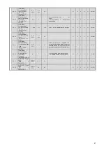
E2-08
Motor Iron-Core
Saturation
Coefficient 2
(Saturation Comp 2)
0.50~
0.75
0.01
0.75
N
N
N
A
A
315H
E2-09
Motor Mechanical
Loss
(Mechanical Loss)
0.0~
10.0
0.1%
0.0
Note: The access level for Open Loop
Vector Control since
VSG126110 has been A
(Advanced).
N
N
N
N
(*)
A
316H
E2-10
Motor Iron Loss for
Torque
Compensation
(Tcomp Iron Loss)
0~
65535
1W
14
**
N
A
A
N
N
317H
E2-11
Motor Rated Output
(Mtr Rated Power)
0.00~
650.00
0.01
kW
0.40
**
**Factory/default settings will vary
based on Control Mode (refer to
attached table).
N
Q
Q
Q
Q
318H
E2-12
Motor Iron
Saturation
Coefficient 3
(Saturation Comp 3)
1.30~
1.60
0.01
1.30
N
N
N
N
N
328H
E3-01
Motor 2 Control
Method Selection
(Control Method)
0~3
1
2
0: V/f Control Mode
1: V/f w/PG Control Mode
2: Open Loop Vector Control Mode
3: Flux Vector Control Mode
N
A
A
A
A
319H
E3-02
Motor 2 Max. Output
Frequency (FMAX)
(Max Frequency)
40.0~
150.0
0.1Hz
50.0
*
N
A
A
A
A
31AH
E3-03
Motor 2 Max. Voltage
(VMAX)
(Max Voltage)
0.0~
255.0
Note-3
0.1
VAC
200.0
Note-3
*
N
A
A
A
A
31BH
E3-04
Motor 2 Max.
Voltage Frequency
(FA)
(Base Frequency)
0.0~
150.0
0.1Hz
50.0
*
N
A
A
A
A
31CH
E3-05
Motor 2 Mid. Output
Frequency (FB)
(Mid Frequency)
0.0~
150.0
0.1Hz
3.0
*
N
A
A
A
F
31DH
E3-06
Motor 2 Mid. Output
Frequency Voltage
(VC)
(Mid Voltage)
0.0~
255.0
Note-3
0.1
VAC
12.0
Note-3
*
N
A
A
A
F
31EH
E3-07
Motor 2 Min. Output
Frequency (FMIN)
(MIn Frequency)
0.0~
150.0
0.1Hz
0.5
*
N
A
A
A
A
31FH
Motor 2 V/f Charactersitics
E3-08
Motor 2Min. Output
Frequency Voltage
(VMIN)
(Min Voltage)
0.0~
255.0
Note-3
0.1
VAC
2.0
Note-3
*
*Factory/default settings will vary
based on Control Mode (refer to
attached table).
N
A
A
A
A
320H
E4-01
Motor 2 Rated
Current
(Motor Rated FLA)
***
0.1A
(*)
1.90
**
N
A
A
A
A
321H
E4-02
Motor 2 Rated Slip
(Motor Rated Slip)
0.00~
20.00
0.01
Hz
2.90
**
N
A
A
A
A
322H
E4-03
Motor 2 No-Load
Current
(No-Load Current)
0.00~
1500.0
Note-4
0.01A
1.20
**
N
A
A
A
A
323H
E4-04
Motor 2 Number of
Poles
(Number of Poles)
2~48
2pole
4
N
N
A
N
A
324H
E4-05
Motor 2
Line-to-Line
Resistance
(Term Resistance)
0.000~
65.000
0.001
Ω
9.842
**
N
A
A
A
A
325H
E4-06
Motor 2 Leak
Inductance
(Motor 2 Leak)
0.0~
40.0
0.1%
18.2
**
N
N
N
A
A
326H
Motor 2 Parameters
E4-07
Motor 2 Rated
Capacity
(Mtr Rated Power)
0.00~
650.00
0.01
kW
0.40
**
(Note) If drive capacity is 7.5kW or
less, then set in units of 0.01A.
** Factory/default settings will vary
based on Control Mode (refer to
attached table).
*** 10% to 200% of the drive’s rated
current can be set.
****The setting range for E4-03 is just
below the range for E4-01
N
A
A
A
A
327H
F1-01
PG Constants
(PG Pulses/Rev)
0~
60000
1
1024
N
N
Q
Q
Q
380H
F1-02
Operation Selection
at PG Open Circuit
(PGO)
(PG Fdbk Loss Sel)
0~3
1
1
0: Deceleration Stop
2: Fast Stop
1: Coast to Stop 3: Alarm Only
N
N
A
N
A
381H
F1-03
Operation Selection
at Overspeed (OS)
(PG Overspeed Sel)
0~3
1
1
0: Deceleration Stop
2: Fast Stop
1: Coast to Stop 3: Alarm Only
N
N
A
N
A
382H
F1-04
Operation Selection
at Deviation
(PG Deviation Sel)
0~3
1
3
0: Deceleration Stop
2: Fast Stop
1: Coast to Stop 3: Alarm Only
N
N
A
N
A
383H
PG Speed Control
F1-05
PG Rotation
(PG Rotation Sel)
0,1
1
0
0: Phase A leads with forward run
command.
1: Phase B leads with forward run
command.
N
N
A
A
A
384H
Note-3: This value is for 200V class drives. Double the value when working with 400V class drives
Note-4: When using Motor 2 via Multi-Function Input (setting = 16), default/factory settings will vary based on drive capacity.
Summary of Contents for CIMR-F7Z
Page 3: ......


