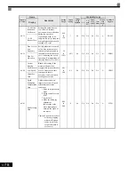
User Parameter Tables
5-
63
* 1. Factory settings will vary based on drive capacity (values given here are for 208-240Vac, 0.4kW).
* 2. Setting value for 208-240Vac. Double the value when working with 380-480Vac drives.
* 3. When set to zero, the motor will accelerate to the speed set acceleration time (C1-01 thru C1-08).
Stall Prevention: L3
User parameters for the stall prevention function are shown in the following table.
L2-06
KEB
Deceleration
Rate
Sets the time required to
decelerate to zero speed when a
KEB command is input from a
multi-function input.
0.0
to
200.0
0.0sec
No
A
A
A
A
A
48AH
KEB Decel
Time
L2-07
Momentary
Recovery
Time
Set the time (in seconds) to
accelerate to the set speed after
recovery from a momentary
power loss. If setting = 0.0,
then active acceleration time is
used instead.
0.0
to
25.5
0.0sec
*3
No
A
A
A
A
A
48BH
UV Return
Time
L2-08
Frequency
Reduction
Gain at
KEB Start
Sets the percentage of output
frequency reduction at the
beginning of deceleration when
a KEB command is input from
multi-function input.
Reduction =
(SlipFreqBeforeKEB) x L2-08
x 2
0
to
300
100%
No
A
A
A
A
A
48CH
KEB
Frequency
Parameter
Number
Name
Description
Setting
Range
Factory
Setting
Change
during
Operation
Control Methods
MODBUS
Register
Display
V/f
V/f
with
PG
Open
Loop
Vector
1
Flux
Vector
Open
Loop
Vector
2
L3-01
Stall
Prevention
Selection
During
Accel
Selects the stall prevention
method used to prevent
excessive current during
acceleration.
0: Disabled - Motor
accelerates at active
acceleration rate. The motor
may stall if load is too
heavy or accel time is too
short.
1: General Purpose - When
output current exceeds
L3-02 level, acceleration
stops. Acceleration will
continue when the output
current level falls below the
L3-02 level.
2: Intelligent - The active
acceleration rate is ignored.
Acceleration is completed
in the shortest amount of
time without exceeding the
current value set in L3-02.
0 to 2
1
No
A
A
A
No
No
48FH
StallP
Accel Sel
Parameter
Number
Name
Description
Setting
Range
Factory
Setting
Change
during
Operation
Control Methods
MODBUS
Register
Display
V/f
V/f
with
PG
Open
Loop
Vector
1
Flux
Vector
Open
Loop
Vector
2
Summary of Contents for CIMR-G7U
Page 2: ......
Page 7: ...v...
Page 32: ...1 18...
Page 90: ...3 16...
Page 112: ...4 22...
Page 382: ...6 164...
Page 410: ...7 28...
Page 454: ......
Page 455: ......


