3.9 Control Circuit Wiring
YASKAWA ELECTRIC
TOEP C710656 10B YASKAWA Power Regenerative Unit - R1000 Instruction Manual
53
El
ect
ri
c
al
In
st
al
la
ti
o
n
3
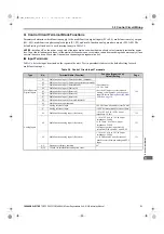
◆
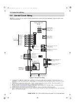
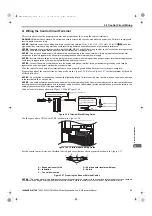
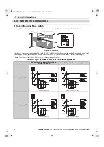
Terminal Configuration
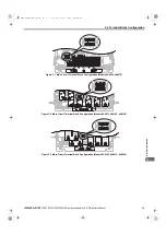
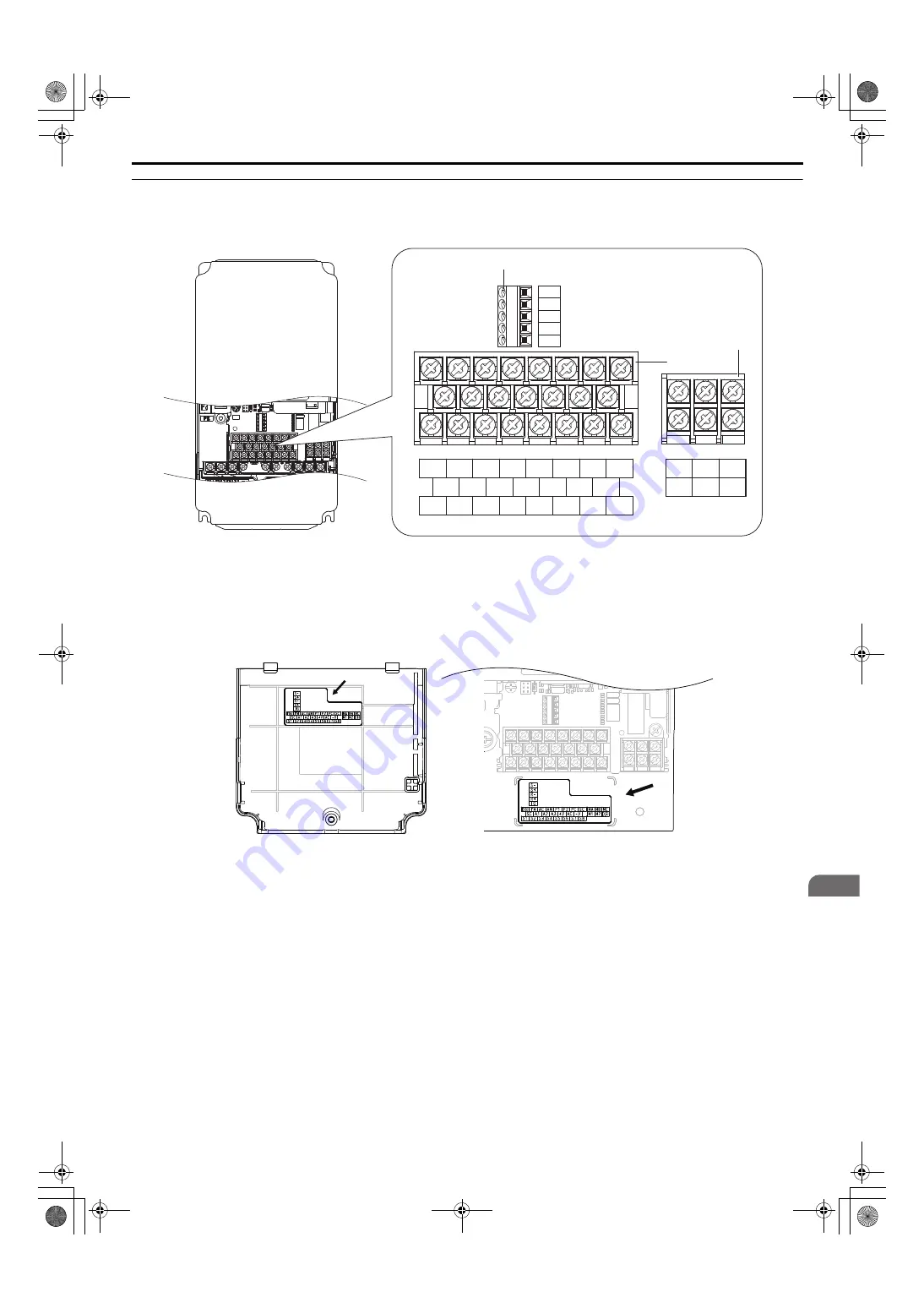
The control circuit terminals are arranged as shown in
.
Figure 3.20
Figure 3.22 Control Circuit Terminal Arrangement
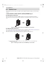
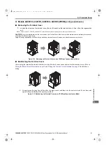
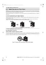
The terminal arrangement is given in one of the locations that are shown in the following figures. The location depends
on the model.
Figure 3.21
Figure 3.23 Location of Terminal Block Arrangement Diagram
A – Terminal Block (TB5)
C – Terminal Block (TB2)
B – Terminal Block (TB1)
IG
R+
R−
S+
S−
E(G) FM AC AM P1 P2 PC SC
MA MB MC
M1 M2 E(G)
S1 S2 S3 S4 S5 S6 S7 S8
SC A1 A2 A3 +V AC -V
A
C
B
YEC
Back of the Terminal Cover
(Models 2A03P5 to 2A0028, and 4A03P5 to 4A0028)
Under the Terminal Blocks
(Models 2A0035 to 2A0105, and 4A0035 to 4A0300)
YEC
TOEP_C710656_10B_1_0.book 53 ページ 2015年1月8日 木曜日 午後8時55分

