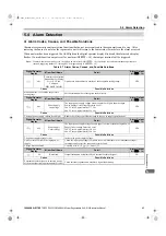
5.4 Alarm Detection
YASKAWA ELECTRIC
TOEP C710656 10B YASKAWA Power Regenerative Unit - R1000 Instruction Manual
97
Tr
oub
le
sho
o
ti
n
g
5
Digital Operator
Display
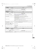
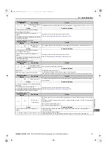
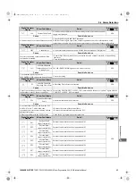
Minor Fault Name
Detail
Alarm Output
(H2-
= 10)
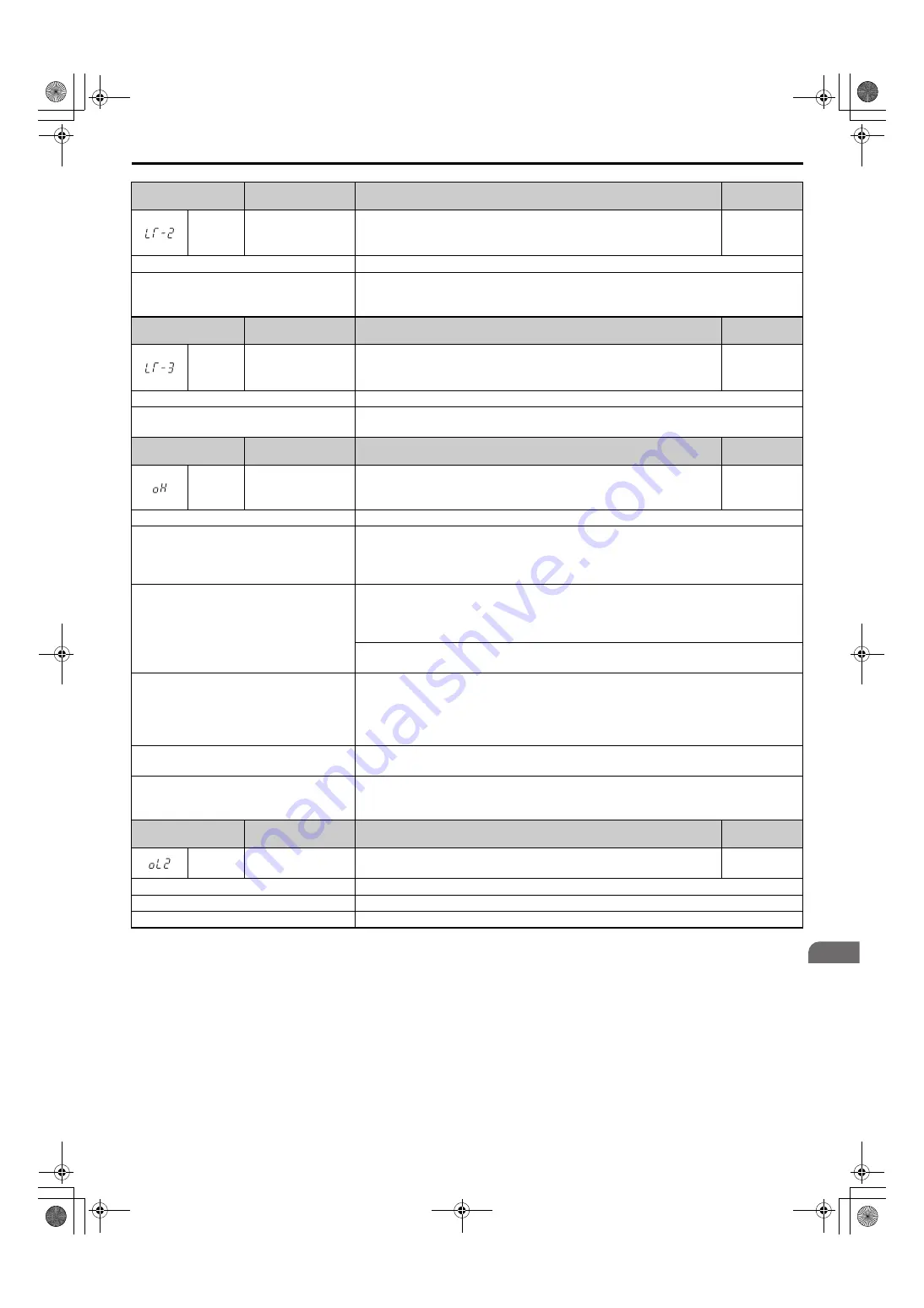
LT-2
Capacitor Maintenance
Time
The main circuit and control circuit capacitors are nearing the end of their
expected performance life.
Note:
An alarm output (H2-
= 10) will only be triggered if H2-
= 2F.
YES
Cause
Possible Solutions
The main circuit and control circuit capacitors
have reached 90% of their expected
performance lives.
Replace either the control board or the entire regenerative unit. For instructions on replacing the
control board, contact Yaskawa or your nearest sales representative.
Digital Operator
Display
Minor Fault Name
Detail
Alarm Output
(H2-
= 10)
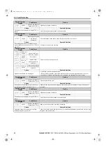
LT-3
Soft Charge Bypass
Relay Maintenance
Time
The DC bus soft charge relay is nearing the end of its expected performance
life.
Note:
An alarm output (H2-
= 10) will only be triggered if H2-
= 2F.
YES
Cause
Possible Solutions
The DC bus soft charge relay has reached 90%
of expected performance life.
Replace either the control board or the entire regenerative unit. For instructions on replacing the
control board, contact Yaskawa or your nearest sales representative.
Digital Operator
Display
Minor Fault Name
Detail
Alarm Output
(H2-
= 10)
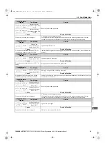
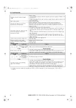
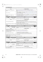
oH
Heatsink Overheat
The temperature of the heatsink exceeded the overheat pre-alarm level set to
L8-02 (90-100
°
C). Default value for L8-02 is determined by o2-04 (Unit
Model Selection).
YES
Cause
Possible Solutions
Surrounding temperature is too high
• Check the surrounding temperature.
• Improve the air circulation within the enclosure panel.
• Install a fan or air conditioner to cool surrounding area.
• Remove anything near regenerative unit that may cause extra heat.
Airflow around the regenerative unit is
restricted.
• Provide proper installation space around the regenerative unit as indicated in the manual. Refer
to
Installation Orientation and Spacing on page 23
for details.
• Allow for the proper space and ensure that there is sufficient circulation around the control
panel.
• Check for dust or other foreign materials clogging the cooling fan.
• Clear debris caught in the fan that restricts air circulation.
The ambient temperature is too high.
Check the ambient temperature.
• Improve ventilation in the control panel.
• Install a cooling device (e.g., a cooling fan or air conditioner) and lower the ambient
temperature.
• If there are heat-generating objects nearby, remove them.
The load is too large.
Measure the output current.
Lower the load.
Internal cooling fan has stopped.
• Replace the cooling fan. Refer to page
for details.
• After replacing the regenerative unit, set parameter o4-03 to 0 to reset the cooling fan operation
time.
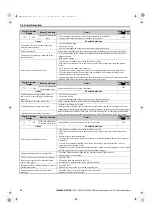
Digital Operator
Display
Minor Fault Name
Detail
Alarm Output
(H2-
= 10)
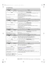
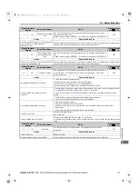
oL2
Overload
The thermal sensor of the regenerative unit triggered the unit overload
protection.
YES
Cause
Possible Solutions
Load is too heavy.
Reduce the load.
The regenerative unit does not operate.
Start regenerative unit operation first, and then start regenerative unit operation.
TOEP_C710656_10B_1_0.book 97 ページ 2015年1月8日 木曜日 午後8時55分

