


n
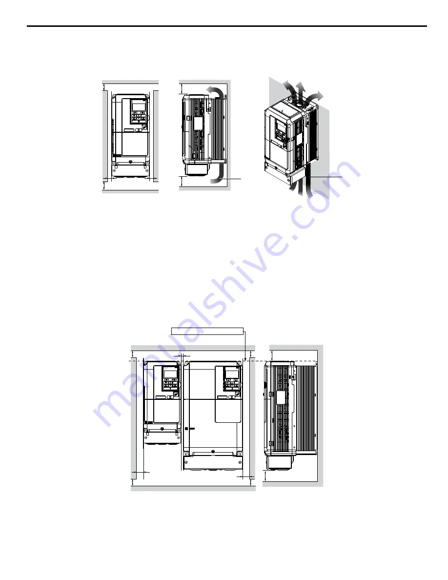
Single Drive Installation
Figure i.2
shows the installation distance required to maintain sufficient space for airflow and wiring. Install the heatsink
against a closed surface to avoid diverting cooling air around the heatsink.
A
A
B
B
Side Clearance
Top/Bottom Clearance
C
C
D
D
A – 50 mm minimum
B – 30 mm minimum
C – 120 mm minimum
D – Airflow direction
Figure i.2 Correct Installation Spacing
Note:
IP20/NEMA 1, UL Type 1 enclosure and IP00/Open Type enclosure models require the same amount of space above and below the drive
for installation.
n
Multiple Drive Installation (Side-by-Side Installation)
Models 5A0003 to 5A0032 can take advantage of Side-by-Side installation.
When installing multiple drives into the same enclosure panel, mount the drives according to
Figure i.2
and set L8-35,
Installation Method Selection, to 1 (Side-by-Side Mounting).
When mounting drives with the minimum clearance of 2 mm according to
Figure i.3
, set parameter L8-35 to 1 while
considering derating.
A
A
A
A
B
C
B
Side Clearance
Line up the tops of the drives.
D
D
Top/Bottom Clearance
A – 50 mm minimum
B – 30 mm minimum
C – 2 mm minimum
D – 120 mm minimum
Figure i.3 Space Between Drives (Side-by-Side Mounting)
Note:
Align the tops of the drives when installing drives of different heights in the same enclosure panel. Leave space between the tops and bottoms
of stacked drives for easier cooling fan replacement.
i.2 Mechanical Installation Safety
YASKAWA TOEP YAIZ1U 02B YASKAWA AC Drive – Z1000 Quick Start Guide
11


