


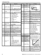
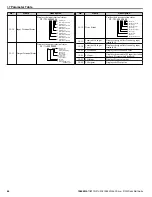
Table i.12 Parameters H3-01 and H3-09 Details
No.
Parameter Name
Description
Setting
Range
Default
Setting
H3-01
Terminal A1 signal level selection
Selects the signal level for terminal A1.
0: 0 to 10 V with Zero Limit
1: 0 to 10 V without Zero Limit
2: 4 to 20 mA Current Input
3: 0 to 20 mA Current Input
0 to 3
0
H3-09
Terminal A2 signal level selection
Selects the signal level for terminal A2.
0: 0 to 10 V with Zero Limit
1: 0 to 10 V without Zero Limit
2: 4 to 20 mA Current Input
3: 0 to 20 mA Current Input
0 to 3
0
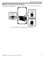
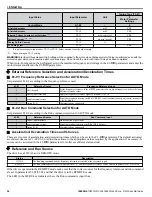
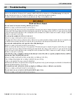
u
Terminal FM/AM Signal Selection
The signal type for terminals FM and AM can be set to either voltage or current output using jumper S5 on the terminal board
as explained in
Table i.13
. When changing the setting of jumper S5, parameters H4-07 and H4-08 must be set accordingly.
The default selection is voltage output for both terminals.
Table i.13 Jumper S5 Settings
Terminal
Voltage Output
Current Output
Terminal FM
AM
FM
V
I
AM
FM
V
I
Terminal AM
AM
FM
V
I
AM
FM
V
I
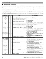
Table i.14 Parameter H4-07 and H4-08 Details
No.
Parameter Name
Description
Setting
Range
Default
Setting
H4-07
Terminal FM signal level selection
0: 0 to 10 Vdc
1: -10 to 10 Vdc
2: 4 to 20 mA
0 to 2
0
H4-08
Terminal AM signal level selection
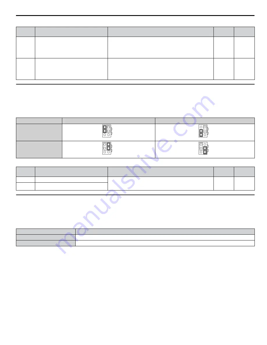
u
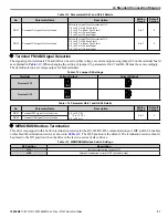
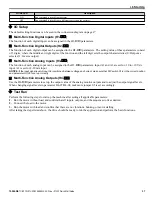
MEMOBUS/Modbus Termination
This drive is equipped with a built-in termination resistor for the RS-422/RS-485 communication port. DIP switch S2 enables
or disabled the termination resistor as shown in
Table i.15
. The OFF position is the default. The termination resistor should
be placed to the ON position when the drive is the last in a series of slave drives.
Table i.15 MEMOBUS/Modbus Switch Settings
S2 Position
Description
ON
Internal termination resistor ON
OFF
Internal termination resistor OFF (default setting)
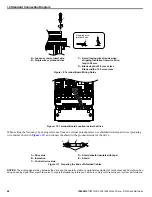
i.4 Standard Connection Diagram
YASKAWA TOEP YAIZ1U 02B YASKAWA AC Drive – Z1000 Quick Start Guide
31


