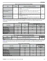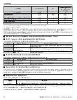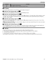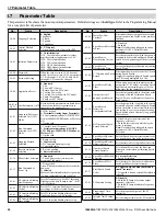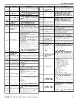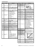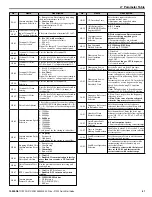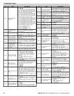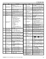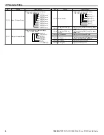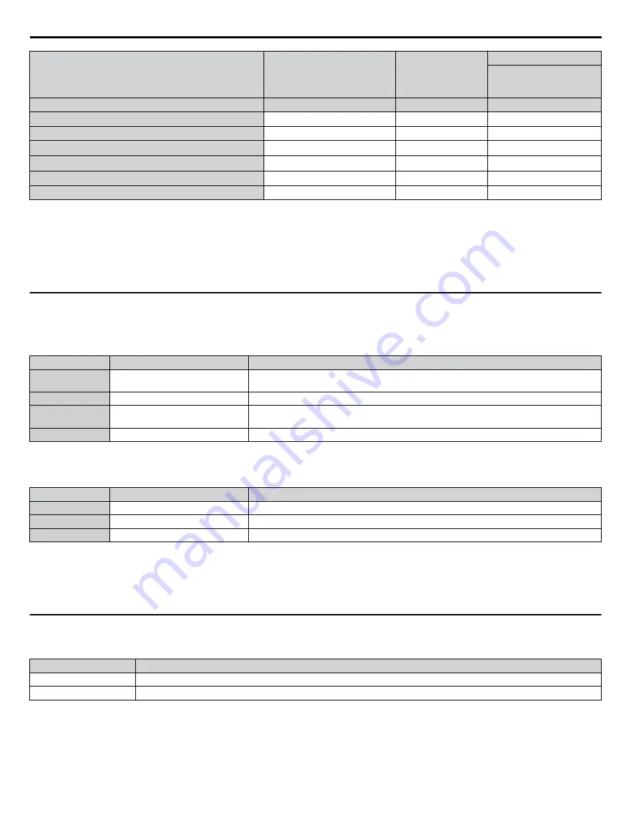
Input Value
Input Parameter
Unit
Tuning Type (T2-01)
0
Motor Parameter
Settings
Control Mode
A1-02
–
5
d-Axis Inductance
T2-11
mH
YES
q-Axis Inductance
T2-12
mH
YES
Induced Voltage Constant Unit Selection
<1>
T2-13
mVs/rad (elec.)
YES
Voltage Constant
<1>
<2>
T2-14
mVmin (mech.)
YES
Tuning Pull-in Current
T2-15
A
–
T2 Tuning Start
T2-18
–
YES
<1> It is only necessary to input either T2-13 or T2-14. Select one and leave the other empty.
<2> Dependent upon T2-13 setting.
WARNING! Electrical Shock Hazard. High voltage will be supplied to the motor when Stationary Auto-Tuning is performed even with the
motor stopped, which could result in death or serious injury. Do not touch the motor until Auto-Tuning has been completed.
When Auto-Tuning cannot be performed, set up the maximum frequency and voltage in the E1-
oo
parameters and enter the
motor data manually into the E2-
oo
parameters.
u
External Reference Selection and Acceleration/Deceleration Times
n
b1-01: Frequency Reference Selection for AUTO Mode
Set parameter b1-01 according to the frequency reference used.
b1-01
Reference Source
Frequency Reference Input
0
HOA keypad
Set the frequency references in the d1-
oo
parameters and use digital inputs to switch over between
different reference values.
1
Analog input terminals
Apply the frequency reference signal to terminal A1 or A2.
2
Serial communications
Serial Communications using the RS-422/RS-485 serial communications port (control terminals R
+, R-, S+, and S-).
3
Option PCB
Communications option card
n
b1-02: Run Command Selection for AUTO Mode
Set parameter b1-02 according to the Run command selection for AUTO mode.
b1-02
Reference Source
Run Command Input
1
Digital input terminals
Multi-Function digital input
2
Serial communications
Serial Communications using the RS-422/RS-485 port
3
Option PCB
Communications option card
n
Acceleration/ Deceleration Times and S-Curves
There are two sets of acceleration and deceleration times which can be set in the C1-
oo
parameters. The default activated
accel/decel times are C1-01/C1-02. Adjust these times to the appropriate values required by the application. If necessary, S-
curves can be activated in the C2-
oo
parameters for softer accel/decel start and end.
u
Reference and Run Source
The drive has a LOCAL and a REMOTE mode.
Status
Description
LOCAL
The Run/Stop command and the frequency reference are entered at the operator keypad.
REMOTE
The Run command source entered in parameter b1-02 and the frequency reference source entered in parameter b1-01 are used.
If the drive is operated in the REMOTE mode, make sure that the correct sources for the frequency reference and run command
are set in parameters b1-01/b1-02 and that the drive is in the REMOTE mode.
The LED in the LO/RE key indicates where the Run command is input from.
i.6 Start Up
36
YASKAWA TOEP YAIZ1U 02B YASKAWA AC Drive – Z1000 Quick Start Guide


