i.7
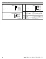
Parameter Table
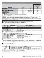
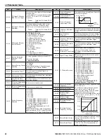
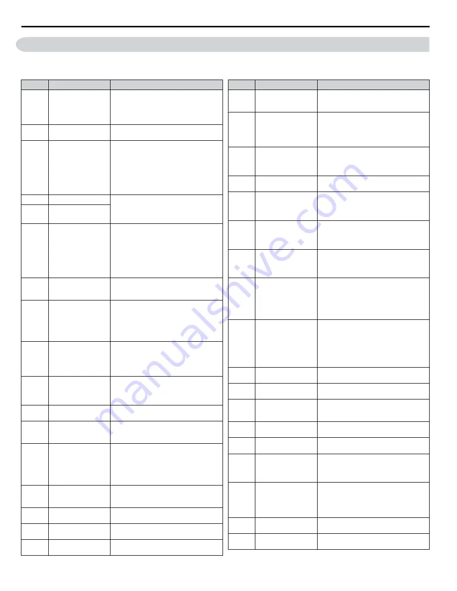
This parameter table shows the most important parameters. Default settings are in
bold type
. Refer to the Programming Manual
for a complete list of parameters.
No.
Name
Description
A1-00
Language Selection
0: English
1: Japanese
3: French
5: Spanish
6: Portuguese
A1-02
Control Method
Selection
0: V/f Control
5: Open Loop Vector Control for PM
A1-03
Initialize Parameters
0: No initialization
1110: User Initialize (parameter values
must be stored using parameter o2-03)
2220: 2-Wire Initialization
3330: 3-Wire Initialization
3410: HVAC Initialization
3420: OEM Bypass Initialization
5550: oPE04 Fault Reset
A1-04
Password
When the value set into A1-04 does not
match the value set into A1-05, parameters
A1-01 through A1-03, A1-06, and A2-01
through A2-33 cannot be changed.
A1-05
Password Setting
A1-06
Application Preset
0: Standard
1: Fan
2: Fan with PI Control
3: Return Fan with PI Control
4: Cooling Tower Fan
5: Cooling Tower Fan with PI Control
6: Pump (Secondary)
7: Pump with PI Control
A2-01 to
A2-32
User Parameters 1 to 32
Recently edited parameters are listed here.
The user can also select parameters to
appear here for quicker access.
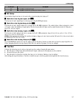
b1-01
Frequency Reference
Selection for AUTO
Mode
0: HOA keypad
1: Terminals (Analog Input Terminals)
2: Serial communications (APOGEE FLN,
BACnet, MEMOBUS/Modbus, or Metasys
N2)
3: Option card
b1-02
Run Command
Selection for AUTO
Mode
1: Control Circuit Terminal
2: Serial communications (APOGEE
FLN, BACnet, MEMOBUS/Modbus, or
Metasys N2)
3: Option card
b1-03
Stopping Method
Selection
0: Ramp to stop
1: Coast to stop
2: DC Injection Braking to stop
3: Coast with timer
b1-04
Reverse Operation
Selection
0: Reverse enabled
1: Reverse disabled
b1-14
Phase Order Selection
0: Standard
1: Switch phase order (reverses the
direction of the motor)
b1-17
Run Command at
Power Up
0: Disregarded
A new Run command must be issued after
power up.
1: Allowed
Motor will start immediately after power up
if a Run command is already enabled.
b2-01
DC Injection Braking
Start Frequency
Sets the frequency at which DC Injection
Braking starts when “Ramp to stop” (b1-03
= 0) is selected.
b2-02
DC Injection Braking
Current
Sets the DC Injection Braking current as a
percentage of the drive rated current.
b2-03
DC Injection Braking
Time at Start
Sets DC Injection Braking time at start.
Disabled when set to 0.00 seconds.
b2-04
DC Injection Braking
Time at Stop
Sets DC Injection Braking time at stop.
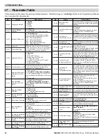
No.
Name
Description
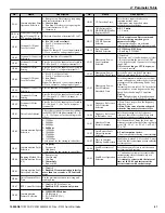
b2-09
Motor Pre-Heat
Current 2
Determines the percentage of motor rated
output current used for the motor pre-heat
function.
b3-01
Speed Search Selection
at Start
0: Disabled
1: Enabled
Note:
Default setting is dependent upon
parameter A1-02, Control Method
Selection.
b3-02
Speed Search
Deactivation Current
Sets the current level at which the speed is
assumed to be detected and Speed Search is
ended. Set as a percentage of the drive rated
current.
b3-03
Speed Search
Deceleration Time
Sets output frequency reduction time during
Speed Search.
b3-04
V/f Gain during Speed
Search
Determines how much to lower the V/f ratio
during Speed Search.
Output voltage during Speed Search equals
the V/f setting multiplied by b3-04.
b3-05
Speed Search Delay
Time
When using an external contactor on the
output side, b3-05 delays executing Speed
Search after a momentary power loss to
allow time for the contactor to close.
b3-06
Output Current 1
during Speed Search
Sets the current injected to the motor at the
beginning of Speed Estimation Speed
Search. Set as a coefficient for the motor
rated current.
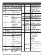
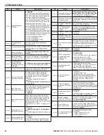
b3-10
Speed Search
Detection
Compensation Gain
Sets the gain which is applied to the speed
detected by Speed Estimation Speed Search
before the motor is reaccelerated. Increase
this setting if ov occurs when performing
Speed Search after a relatively long period
of baseblock.
b3-14
Bi-Directional Speed
Search Selection
0: Disabled (uses the direction of the
frequency reference)
1: Enabled (drive detects which way the
motor is rotating)
Note:
Default setting is dependent upon
parameter A1-02, Control Method
Selection.
b3-17
Speed Search Restart
Current Level
Sets the Speed Search restart current level
as a percentage of the drive rated current.
b3-18
Speed Search Restart
Detection Time
Sets the time to detect Speed Search restart.
b3-19
Number of Speed
Search Restarts
Sets the number of times the drive can
attempt to restart when performing Speed
Search.
b3-24
Speed Search Method
Selection
0: Current Detection
1: Speed Estimation
b3-25
Speed Search Wait
Time
Sets the time the drive must wait between
each Speed Search restart attempt.
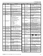
b3-27
Start Speed Search
Select
0: Triggered when a Run command is
issued. (normal).
1: Triggered when an external baseblock is
released.
b5-01
PI Function Setting
0: Disabled
1: Enabled (PI output becomes output
frequency reference)
3: Enabled (PI output added to frequency
reference)
b5-02
Proportional Gain
Setting (P)
Sets the proportional gain of the PI
controller.
b5-03
Integral Time Setting
(I)
Sets the integral time for the PI controller.
i.7 Parameter Table
38
YASKAWA TOEP YAIZ1U 02B YASKAWA AC Drive – Z1000 Quick Start Guide


