u
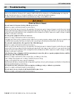
General Faults and Alarms
Faults and alarms indicate problems in the drive or in the machine.
An alarm is indicated by a code on the data display and the flashing ALM LED. The drive output is not necessarily switched
off.
A fault is indicated by a code on the data display and an illuminated ALM LED. The drive output is always switched off
immediately and the motor coasts to stop.
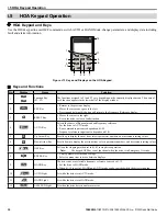
To remove an alarm or reset a fault, trace the cause, remove it and reset the drive by pushing the Reset key on the HOA keypad
or cycling the power supply.
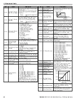
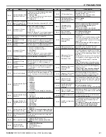
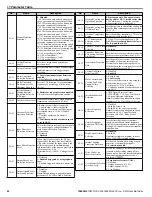
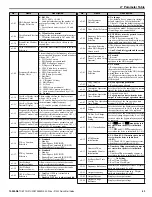
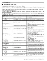
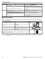
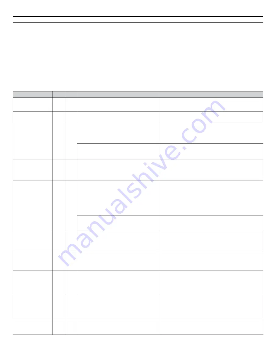
The table below lists the most important alarms and faults and most common causes and possible solutions. Refer to the drive
User Manual for a complete list.
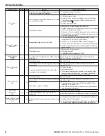
HOA Keypad
ALM FLT
Cause
Possible Solution
HOA Keypad Battery
Voltage Low
bAT
O
O
The HOA keypad battery is low
Replace the HOA keypad battery.
Baseblock
bb
O
External baseblock signal was entered via one of
the multi-function input terminals (S1 to S7).
Check external sequence and baseblock signal input timing.
Option
Communication Error
bUS
O
O
Connection is broken or master controller
stopped communicating.
• Check for faulty wiring.
• Correct the wiring.
• Check for disconnected cables and short circuits. Repair as
needed.
The option is not properly connected to the drive.
• The connector pins on the option are not properly lined up
with the connector pins on the drive.
• Reinstall the option.
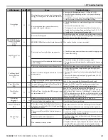
Serial Communication
Transmission Error
CALL
O
Communications wiring is faulty, there is a short
circuit, or something is not connected properly.
• Check for wiring errors.
• Correct the wiring.
• Check for disconnected cables and short circuits. Repair as
needed.
MEMOBUS/Modbus
Communication Error
CE
O
O
A data error occurred due to noise.
• Check options available to minimize the effects of noise.
• Take steps to counteract noise in the control circuit wiring,
main circuit lines, and ground wiring.
• Reduce noise on the controller side.
• Separate all wiring for communication devices from drive
input power lines. Install an EMC noise filter to the drive
input power supply.
Communication protocol is incompatible.
• Check the H5 parameter settings and the protocol setting in
the controller.
• Ensure settings are compatible.
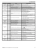
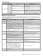
Control Circuit Error
CPF11 to CPF14
CPF16 to CPF19
O
There is a self-diagnostic error in the control
circuit
• Cycle power to the drive.
• If the problem continues, replace the control board or the
entire drive. Contact Yaskawa or a Yaskawa representative
for instructions on replacing the control board.
A/D Conversion Error
CPF02
O
Control circuit is damaged
• Cycle power to the drive.
• If the problem continues, replace the control board or the
entire drive. Contact Yaskawa or a Yaskawa representative
for instructions on replacing the control board.
Control Board
Connection Error
CPF03
O
There is a connection error
• Turn off the power and check the connection between the
control board and the drive.
• If the problem continues, replace the control board or the
entire drive. Contact Yaskawa or a Yaskawa representative
for instructions on replacing the control board.
EEPROM Memory
Data Error
CPF06
O
There is an error in EEPROM control circuit
• Turn off the power and check the connection between the
control board and the drive.
• If the problem continues, replace the control board or the
entire drive. Contact Yaskawa or a Yaskawa representative
for instructions on replacing the control board.
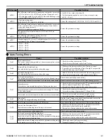
Cannot Reset
CrST
O
Fault reset was being executed when a Run
command was entered.
• Ensure that a Run command cannot be entered from the
external terminals or option during fault reset.
• Turn off the Run command.
i.8 Troubleshooting
46
YASKAWA TOEP YAIZ1U 02B YASKAWA AC Drive – Z1000 Quick Start Guide

