3 Startup Procedure and Test Run
216
YASKAWA ELECTRIC
SIEP C710617 19A YASKAWA AC Drive CR700 Technical Manual
Torque and current are proportionally related when flux is constant. These are possible methods for suppressing
current at start.
•
Method 1: Quickly generate flux.
–
Initial excitation
–
DC Inject Braking at Start
–
Magnetic Flux Compensation
•
Method 2: If using V/f control or OLV control, set the highest value possible for the V/f pattern.
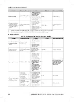
Table 3.28 How To Generate Flux Quickly and its Effectiveness
Type
Description
Basic type
There is a delay in magnetic flux developing after start.
Secondary circuit time constant: The value of [T] is
displayed in the drive monitor as the torque reference, so it
is possible to see that the torque limit is not operating if
magnetic flux compensation is active. However, the torque
limit is [Iq] limit, so it is not a problem in this situation.
The effectiveness of the torque limit can be confirmed by
checking the current level.
Initial
Excitation
through an
External
Terminal
(CLV only)
-
DC Inject
Braking at Start
(All control
methods)
It is possible to start operating after a bit of flux has built
up. However, it can take over 1 s for flux to build up in
mid-sized motors. Some adjustment is necessary because
waiting for over 1 s will decrease the responsiveness of the
drive.
Note:
Usually, set between 0.2 s and 0.3 s.
Magnetic Flux
Compensation
(OLV Control)
The purpose of this function is to build up magnetic flux
more quickly by allowing a large amount of flux current to
flow at start using the percentage set in
b2-08 [Magnetic
Flux Compensation Value]
. Magnetic flux compensation of
200% generates 1/2 for the flux build up.
Note:
Set
b2-03 [DC Inject Braking Time at Start]
to adjust
this level.
Field Forcing
The upper limit value for
d6-06 [Field Forcing Limit]
is
400%, which allows flux current to flow at start up for the
purpose of compensating for the delay in flux build up. If
the value set in
d6-06
is set too high, this will increase the
amount of lurching at start. Set an appropriate value
between 200% and 400%.
Note:
Speed Control must be active to make these
adjustments. You cannot make adjustments during DC
Injection Braking at start or at stop.
*1
Field Forcing is enabled when
d6-03 = 1 [Field Forcing Selection = Enabled]
, and when using CLV control or OLV control.
◆
Controllability Problems and Possible Solutions
The following explains the adjustment procedures to follow when issues such as hunting or oscillation attributable
to control functionality occur during a test run. Adjust the relevant parameters appearing in the chart, in
accordance with the control method being used and the drive status.


