3 Startup Procedure and Test Run
YASKAWA ELECTRIC
SIEP C710617 19A YASKAWA AC Drive CR700 Technical Manual
223
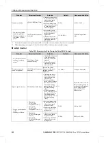
Problem
Parameter Number
Solution
Default
Recommended Value
Speed response cannot be
secured for low speed or
high speed.
•
C5-07 [ASR Gain
Switchover Frequency]
•
High speed
C5-01 [ASR
Proportional Gain 1]
C5-02 [ASR Integral
Time 1]
•
Low speed
C5-03 [ASR
Proportional Gain 2]
C5-04 [ASR Integral
Time 2]
Change the ASR
proportional gain and
ASR integral time in
accordance with the
output frequency.
0.0 Hz
0.0 Hz to maximum output
frequency
Hunting, oscillation
C5-06 [ASR Delay Time]
•
Decrease setting value
in increments of 0.010
when torque, speed
response is slow.
•
Increase setting value
when vibration is likely
to occur due to poor
machine rigidity.
0.004 s
0.004 s to 0.020 s
*1
Differs depending on setting for
o2-04 [Drive Model (KVA) Selection]
, when at default settings.
*2
Differs depending on setting for
o2-04 [Drive Model (KVA) Selection]
, when at default settings.
*3
For more information about speed control (ASR), refer to the section where the
C5 parameter
is explained.
*4
The optimal values for a no-load operation can differ from the optimal values for actual loading operation.
◆
Test Run Checklist
Review the following checklist and check each item before performing a test run.
Check
No.
Description
1
Thoroughly read this manual before performing a test run.
2
Check the
“
Wiring Checklist
”
.
3
Energize the drive.
4
Set the voltage for the power supply to
E1-01 [Input AC Supply Voltage]
.
Check the items that correspond to the control method being used.
WARNING
Sudden Movement Hazard. Correctly wire the start/stop and safety circuits and make sure that the drive
operates correctly when the drive is energized. Failure to obey can cause death or serious injury from moving equipment.
Table 3.33 V/f Control [A1-02 = 0] and Closed Loop V/f Control [A1-02 = 1]
Check
No.
Description
5
Select the best V/f pattern according to the application and motor characteristics.
Example: If you use a motor with a rated frequency of 60 Hz, set
E1-03 = 1 [V/f Pattern Selection = Const Trq,
60Hz base, 60Hz max]
as a standard V/f pattern.
Table 3.34 Closed Loop V/f Control [A1-02 = 1]
Check
No.
Description
6
Set
F1-01 [Encoder 1 Pulse Count (PPR)]
correctly and make sure the encoder pulse counting direction is
correct.
7
Set
C5-01 [ASR Proportional Gain 1] and C5-02 [ASR Integral Time 1]
.


