692
YASKAWA ELECTRIC
SIEP C710617 19A YASKAWA AC Drive CR700 Technical Manual
•
Set parameters correctly.
•
Parameter setting values may be changed after performing Auto-Tuning.
•
Design the system that can prevent the vertical axis from falling if the drive fails.
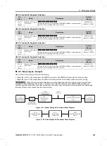
The following figure illustrates the relationship between torque limits via parameters and torque limits via analog
input.
Figure 11.79 Torque Limits via Parameters and Analog Inputs
11: Reverse Torque Limit
Setting
Function
Description
11
Reverse Torque Limit
Enters the load torque limit if the motor rated torque is 100%.
Note:
When you use
L7-01 to L7-04
and analog inputs to set torque limits for the same quadrant, it will enable the lower torque limit.
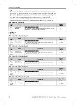
12: Regenerative Torque Limit
Setting
Function
Description
12
Regenerative Torque
Limit
Enters the regenerative torque limit if the motor rated torque is 100%.
Note:
When you use
L7-01 to L7-04
and analog inputs to set torque limits for the same quadrant, it will enable the lower torque limit.
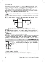
14: Torque Compensation
Setting
Function
Description
14
Torque
Compensation
Inputs the torque compensation value assuming that the motor rated torque is 100%.
15: General Torque Limit
Setting
Function
Description
15
General Torque Limit
Enters the torque limit that is the same for all quadrants for forward, reverse, and regenerative
operation if the motor rated torque is 100%.
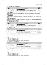
1F: Not Used
Setting
Function
Description
1F
Not Used
Value for terminals that are not being used or terminals being used in through mode.
When you set a terminal that you do not use to 1F, you can use the signal that is input to that terminal as the PLC
analog signal input from MEMOBUS/Modbus communications or the communication option. This input signal
does not have an effect on drive operation. This signal functions the same as F (Through Mode).
V/f
CL-V/f
OLV
CLV
AOLV
V/f
CL-V/f
OLV
CLV
AOLV
V/f
CL-V/f
OLV
CLV
AOLV
V/f
CL-V/f
OLV
CLV
AOLV
V/f
CL-V/f
OLV
CLV
AOLV


