710
YASKAWA ELECTRIC
SIEP C710617 19A YASKAWA AC Drive CR700 Technical Manual
Note:
•
The upper limit of this setting is determined by
L8-38 [Carrier Frequency Reduction]
.
•
Motors may stall if continuing to operate at default settings when motor output is small relative to drive capacity. Decrease the setting
value if stalls occur.
•
When you operate the motor in the constant power range, set
L3-03 [Stall Prevent Limit during Accel]
.
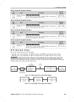
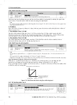
L3-03: Stall Prevent Limit during Accel
No.
(Hex.)
Name
Description
Default
(Range)
L3-03
(0491)
Stall Prevent Limit
during Accel
Sets the lower limit for the stall prevention level during acceleration used
for constant output ranges as a percentage of the drive rated output current.
50%
(0 - 100%)
The stall prevention level set in
L3-02 [Stall Prevent Level during Accel]
is automatically reduced when the motor
is running within the constant output range. Parameter
L3-03
is the limit value used to prevent the stall prevention
level during constant output ranges to fall below the minimum required level.
Note:
The function to automatically reduce the stall prevention level does not operate when
L3-01 = 3 [Stall Prevention during Accel =
Current Limit Method]
.
Figure 11.91 Stall Prevent Level during Accel/Limit
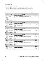
L3-04: Stall Prevention during Decel
No.
(Hex.)
Name
Description
Default
(Range)
L3-04
(0492)
Stall Prevention
during Decel
Sets the method that the drive will use to prevent overvoltage faults when
decelerating.
0
(0 - 5)
Note:
To connect a dynamic braking option (braking resistor or braking resistor unit) to the drive, set this parameter to 0 or 3. If this parameter
is set to a value other than 0 or 3, then the Stall Prevention function during deceleration will be enabled, and the dynamic braking option
will not function.
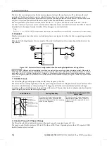
Stall Prevention during deceleration controls the deceleration as specified by the DC bus voltage and does not let
high inertia or fast deceleration cause
ov [Overvoltage]
faults.
0 : Disabled
The drive decelerates as specified by the deceleration time. If the deceleration time is too short, the drive can
detect an
ov
fault.
Note:
If an
ov
fault occurs, connect a dynamic braking option to the drive. If an
ov
fault occurs while operating the drive with a dynamic
braking option and
A1-02 = 0 or 2 [Control Method Selection = V/f Control, Open Loop Vector]
and
L3-04 = 0
, set
L3-04 = 3
.
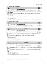
1 : General Purpose
The drive decelerates as specified by the deceleration time. When the DC bus voltage is more than the Stall
Prevention level during deceleration, the drive stops deceleration and continues operation at the current frequency.
The drive resumes deceleration at the set deceleration time once the DC bus voltage drops below the stall
prevention level. Frequent use of Stall Prevention will help prevent
ov
faults when the deceleration time is set
shorter than the drive can usually accept.
Note:
The Stall Prevention during Deceleration function will increase the deceleration time to stop and the deceleration time will be longer
than the setting. This function is not applicable for applications such as conveyors, where the precision of the stop position is very
important. Consider using a dynamic braking option instead in such applications.
V/f
CL-V/f
OLV
CLV
AOLV
V/f
CL-V/f
OLV
CLV
AOLV


