background image

4  LCD Operator Option Components

YASKAWA

 TOBP C730600 29A V1000 Option LCD Operator Installation Manual


15

LCD Operator LED Status Indicators

Table 7  LED Status and Meaning

Figure 3

Figure 3  RUN LED Status

LED

Illuminated

Flashing

<1>

<1> For the difference between “Flashing” and “Flashing Quickly” of the RUN LED, refer to 

Figure 3

, RUN LED 

Status.

Flashing 

Quickly

<1>

Off

LO/RE 

LED

When the run 
command is selected 
from the LCD 
operator (LOCAL).

Run command is 
selected from a 
device other than the 
LCD operator 
(REMOTE).

RUN LED

During run.

• During 

deceleration to 
stop.

• When a run 

command is input 
and the frequency 
reference is 0 Hz.

• During 

deceleration at a 
fast-stop.

• During stop by 

External Fault 
digital input.

During stop.

As shown

RE

LO

RUN

Flashing 

quickly

Flashing

O

N

O

N

O

N

O

N

O

N

O

N

1 s

Summary of Contents for Drive-V1000

Page 1: ...properly use the product read this manual thoroughly and retain for easy reference inspection and maintenance Ensure the end user receives this manual Installation Manual LCD Operator YASKAWA AC Driv...

Page 2: ...ior written permission of Yaskawa No patent liability is assumed with respect to the use of the information contained herein Moreover because Yaskawa is constantly striving to improve its high quality...

Page 3: ...on Manual 3 Table of Contents 1 PREFACE AND SAFETY 4 2 PRODUCT OVERVIEW 8 3 RECEIVING 10 4 LCD OPERATOR OPTION COMPONENTS 12 5 INSTALLATION PROCEDURE 20 6 BASIC OPERATION 25 7 RELATED PARAMETERS 33 8...

Page 4: ...r sole safety control Without exception all controls should be designed to detect faults dynamically and fail safely under all circumstances All systems or equipment designed to incorporate a product...

Page 5: ...skawa com Europe http www yaskawa eu com Japan https www e mechatronics com Other areas contact a Yaskawa representative For questions contact the local Yaskawa sales office or the nearest Yaskawa rep...

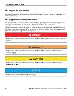
Page 6: ...anual and local codes The following conventions are used to indicate safety messages in this manual Failure to heed these messages could result in serious or possibly even fatal injury or damage to th...

Page 7: ...e content and presentation of the manual may be changed without notice to improve the product and or the manual When ordering a new copy of the manual due to damage or loss contact your Yaskawa repres...

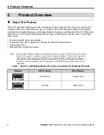
Page 8: ...d copy drive parameter settings to another Yaskawa drive Operate the drive Monitor drive operation status Note When the LCD Operator Option is installed and connected to the V1000 it will cause the dr...

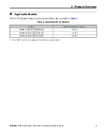
Page 9: ...ation Manual 9 Applicable Models The LCD Operator Option can be used with the drive models in Table 2 Table 2 Applicable Drive Models Drive Drive Software Version 1 1 See PRG on the drive nameplate fo...

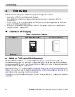
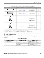
Page 10: ...3 Contents of Package Additional Part Required Sold Separately Proper installation of the LCD Operator Option requires a communication cable A communication cable is not provided A connection cable ca...

Page 11: ...UTP Cat 5e cable Sold Separately 24 Communication Cable 3 m 72606 WV003 2 Sold Separately 24 Installation Support Set A 100 039 992 Sold Separately For use with holes through the panel 22 Installatio...

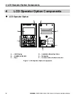
Page 12: ...tion Components LCD Operator Option Figure 1 Figure 1 LCD Operator Option Components A LCD Display D Installation Mounting Holes B ALARM ALM LED E Nameplate C Keys F Communication Cable Connector MODE...

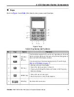
Page 13: ...layed The name of each function appears in the lower half of the display window For a description of functions assigned to the F1 and F2 keys Refer to LCD Display on page 17 2 ESC Key Returns to the p...

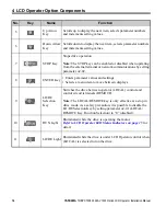
Page 14: ...TER Key Enters parameter values and settings Selects a menu item to move between displays 9 LO RE Selection Key Switches the drive between operator LOCAL control and control circuit terminals REMOTE N...

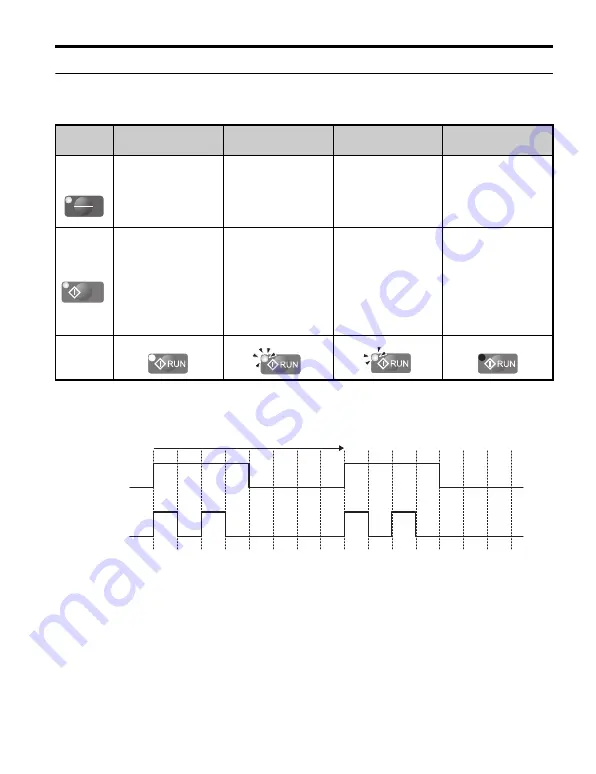
Page 15: ...kly of the RUN LED refer to Figure 3 RUN LED Status Flashing Quickly 1 Off LO RE LED When the run command is selected from the LCD operator LOCAL Run command is selected from a device other than the L...

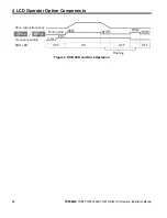
Page 16: ...ASKAWA TOBP C730600 29A V1000 Option LCD Operator Installation Manual Figure 4 Figure 4 RUN LED and Drive Operation Drive output frequency During stop Frequency setting OFF ON Flashing OFF OFF RUN LED...

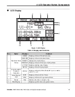
Page 17: ...n Monitor Mode VERIFY Indicates the Verify Menu PRMSET Displayed when in Parameter Setting Mode A TUNE Displayed during Auto Tuning SETUP Displayed when in Setup Mode 2 DriveWorksEZ Function Selection...

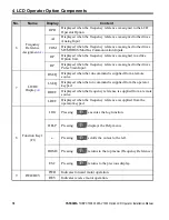
Page 18: ...e is assigned to the drives Pulse Train Input 7 LO RE Display 2 RSEQ Displayed when the run command is supplied from a remote source LSEQ Displayed when the run command is supplied from the operator k...

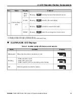
Page 19: ...the next display Pressing scrolls the cursor to the right RESET Pressing resets the existing drive fault or error 1 Displayed when in Frequency Reference Mode 2 Displayed when in Frequency Reference...

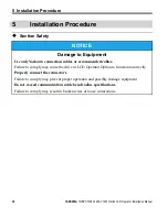
Page 20: ...ly Yaskawa connection cables or recommended cables Failure to comply may cause the drive or LCD Operator Option to function incorrectly Properly connect the connectors Failure to comply may prevent pr...

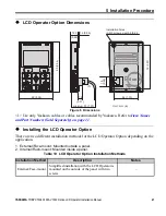
Page 21: ...on depending on the application 1 External Face mount Mounted outside a panel 2 Internal Flush mount Mounted inside a panel Table 10 LCD Operator Option Installation Methods Installation Method Descri...

Page 22: ...ure 7 Figure 7 External Face mount Installation Figure 8 Figure 8 Panel Cut out Dimensions External Face mount Installation Internal Flush mount Encloses the LCD Operator Option in the panel The LCD O...

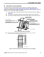
Page 23: ...igure 10 2 Mount the LCD Operator Option to the installation support sold separately 3 Mount the installation support and LCD Operator Option to the enclosure panel Figure 9 Figure 9 Internal Flush Mo...

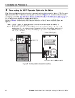
Page 24: ...CD Operator or drive to malfunction Note The STOP key on the drives built in LED operator is the only functional key on the built in LED operator when the LCD Operator Option is connected to the drive...

Page 25: ...d1 01 U1 01 000 00Hz 3 4 0 00 60 00 0 00Hz DRV FWD Rdy MODE U1 01 0 00Hz U1 02 0 00Hz U1 03 0 00A DRV Monitor Menu Rdy MODE PRG Modified Consts HELP HELP DATA MODE PRG Quick Setting DATA HELP MODE PR...

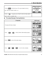
Page 26: ...LCD Display 1 Apply main power to the drive The Frequency Reference appears after the initial display on the LCD Operator Option 2 Press to show the Frequency Reference display If b1 01 is not set to...

Page 27: ...ce display 2 Press until the Monitor Menu display appears 3 Press to show the Monitor display 4 Press to view the drive monitors RUN MONITR FREF d1 01 U1 01 006 00Hz 0 00 60 00 0 00Hz DRV FWD Rdy MODE...

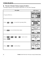
Page 28: ...quency Reference 2 Press to select the Programming Mode 3 Press to show the Initialization display 4 Press to select A1 00 and press 5 Press to enter setting 1 MODE U1 01 0 00Hz U1 02 0 00Hz U1 03 0 0...

Page 29: ...he LCD Operator Option will display Japanese Procedure LCD Screen 1 Frequency Reference diplay 2 Press to select the Programming Mode 3 Press to show the Initialization display 4 Press to select param...

Page 30: ...ption can perform the Read function an estimated 100 000 times Copy Copies the parameter settings from the LCD Operator Option to another Yaskawa drive Verify Verifies that parameter settings in the d...

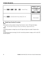
Page 31: ...ngs in the LCD Operator Option Procedure LCD Screen 1 Frequency Reference display 2 Press to select the Programming Mode 3 Press to show the Initialization display 4 Press to select o3 01 and press 5...

Page 32: ...600 29A V1000 Option LCD Operator Installation Manual 6 Press and the LCD Operator Option will read the parameter settings from the drive 7 Automatically return to the Copy Function Selection display...

Page 33: ...Digital preset speed d1 01 to d1 17 1 Terminals Analog input terminal A1 or A2 2 MEMOBUS Modbus serial communications 3 Option PCB 4 Pulse Input Terminal RP 1 b1 02 Run Command Selection 1 Selects th...

Page 34: ...n Selection when LCD Operator Option is Disconnected Sets drive action when the LCD Operator Option is removed in LOCAL mode or with b1 02 0 0 The drive will continue operation 1 The drive will trigge...

Page 35: ...artment if the cable appears to be connect properly but still no message appears to indicate the error Table 12 Fault Error Code Displays LCD Operator LED Operator Description 1 LCD Operator Option is...

Page 36: ...nnect LCD Operator Option Connection Fault oPr Data should appear on the LED operator By reconnecting the LCD operator to the drive data should also appear on the LCD Operator display An oPr fault wil...

Page 37: ...The LCD display may respond more slowly if the ambient temperature falls below freezing Higher temperatures can also shorten the performance life of the LCD display Humidity up to 95 RH no condensati...

Page 38: ...sion History The revision dates and numbers of the revised manuals are given on the bottom of the back cover Date of Published Rev No Section Revised Content November 2007 First edition MANUAL NO TOBP...

Page 39: ...hone 1 847 887 7000 Fax 1 847 887 7370 YASKAWA ELETRICO DO BRASIL LTDA Avenida Fagundes Filho 620 Bairro Saude Sao Paulo SP Brazil CEP 04304 000 Phone 55 11 3585 1100 Fax 55 11 5581 8795 YASKAWA ELECT...

Reviews: