14.3 Settings
14.3.1 Block Diagram
14-5
14
Operation with Serial Command Communications
14.3
Settings
This section explains the settings for the INDEXER Module’s serial commands.
14.3.1
Block Diagram
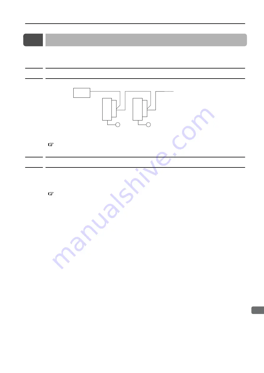
The following block diagram shows the basic connections for multi-axis control.
Refer to the following section for information on wiring.
4.6 Serial Command Communications Connector (CN12)
14.3.2
Setting the Axis Address
Axis addresses can be set with parameter Pn010 (axis address selection). Set an axis address
in the range 1 to F. If an address outside this range is set, serial command communications will
not be performed. Refer to the following section for information on the parameter setting meth-
ods.
5.1 Manipulating Parameters (Pn
Note: With the INDEXER Module (NS600) for SGDH SERVOPACKs, axis addresses were set with rotary switches,
but with INDEXER Modules (SGDV-OCA03A) for SGDV SERVOPACKs, axis addresses are set in the parame-
ters.
#1
#2
SER
VOP
ACK
CN12
CN12
M
M
Host
controller
Up to 16 axes can be connected.
SER
VOP
ACK


