background image

9  Adjustments

9-20

9.5  Analog Monitor

Signals for analog voltage references can be monitored. 
To monitor analog signals, connect the analog monitor cable (JZSP-CA01 or DE9404559) to the connector CN5.
The analog monitor signals can be selected by setting parameters Pn003.0 and Pn003.1.

Pin Number

Line Color

Signal Name

Monitoring Item with Factory Setting

1

Red

Analog monitor 2

Motor speed: 1 V/1000 min

-1

2

White

Analog monitor 1

Torque reference: 1 V/100% rated torque 

3, 4

Black (2 lines)

GND (0 V)

Analog monitor cable model:
JZSP-CA01 or DE9404559

Black

Black

Red

White

CN3

CN8

BATTERY

MODE/SET

DATA/

POWER

CN5

6

&#6#

5'

'

/1& 

4

1

2

'

4

#

6

1

%0

%0

219'4

%0

Artisan Technology Group - Quality Instrumentation ... Guaranteed | (888) 88-SOURCE | www.artisantg.com

Summary of Contents for E-II Series

Page 1: ...nderutilized and idle equipment along with credit for buybacks and trade ins Custom engineering so your equipment works exactly as you specify Critical and expedited services Leasing Rentals Demos In...

Page 2: ...Peripheral Devices Wiring Digital Operator Panel Operator Operation Adjustments Inspection Maintenance and Troubleshooting Appendix MANUAL NO SIEP S800000 59A 1 2 3 4 5 6 7 8 9 10 11 SGMVH SGDM SGDH C...

Page 3: ...f the information contained herein Moreover because Yaskawa is con stantly striving to improve its high quality products the information contained in this manual is subject to change without notice Ev...

Page 4: ...ents of II Series servo drives Those maintaining or inspecting II Series servo drives Description of Technical Terms The terms in this manual are defined as follows Servomotor or motor II Series SGMVH...

Page 5: ...otors and Peripheral Devices Ratings and Character istics System Design Panel Configura tion and Wiring TrialOperation and Servo Adjustment Inspection and Maintenance Chapter 1 Outline 9 Chapter 2 Sel...

Page 6: ...t for the II Series servomotor II Series SGDH Fully Closed Interface Unit User s Manual Type JUSP FC100 SIE C718 5 Provides detailed information on the fully closed con trol of the JUSP FC100 interfac...

Page 7: ...d could result in relatively serious or minor injury damage to the product or faulty operation In some situations the precautions indicated could have serious consequences if not heeded Indicates proh...

Page 8: ...xecuted when an incorrect value is set in Pn205 an incorrect value will be set in the encoder The alarm will disappear even if an incorrect value is set but incorrect positions will be detected result...

Page 9: ...reat packing materials such as wooden frames pallets or plywood the packing materials must be treated before the product is packaged and methods other than fumigation must be used Example Heat treatme...

Page 10: ...may result in burns or fire Method 1 Wire the output from the thermal protector to the host controller and turn OFF the servo when the thermal protector operates Method 2 Wire the thermal protector to...

Page 11: ...us to install batteries at both simultaneously because that sets up a loop circuit between the batteries Be sure to wire correctly and securely Failure to observe this caution may result in motor over...

Page 12: ...e at occurrence of overtravel Failure to observe this caution may cause workpieces to fall off due to overtravel Do not touch the SERVOPACK heatsinks regenerative resistor or servomotor while power is...

Page 13: ...ys replace the cover or protective guard as specified first and then operate the products in accordance with the manual The drawings presented in this manual are typical examples and may not match the...

Page 14: ...cting Peripheral Devices 2 6 2 5 1 Special Options 2 6 2 5 2 Molded case Circuit Breaker and Fuse Capacity 2 8 2 5 3 Noise Filters Magnetic Contactors and Brake Power Supply Units 2 9 2 5 4 Regenerati...

Page 15: ...d Allowable Load Moment of Inertia 4 12 4 5 1 Overload Characteristics 4 12 4 5 2 Starting and Stopping Time 4 13 4 5 3 Load Moment of Inertia 4 14 4 6 SERVOPACK Dimensional Drawings 4 16 4 6 1 Three...

Page 16: ...15 MECHATROLINK Application Module 5 41 5 5 16 DeviceNet Application Module 5 42 5 5 17 PROFIBUS DP Application Module 5 43 5 5 18 Fully closed Application Module 5 44 6 Wiring 6 1 Wiring Main Circuit...

Page 17: ...eter Setting Mode Pn 7 21 7 3 1 Setting Parameters 7 21 7 3 2 Input Circuit Signal Allocation 7 24 7 3 3 Output Circuit Signal Allocation 7 27 7 4 Operation in Monitor Mode Un 7 29 7 4 1 List of Monit...

Page 18: ...tion INHIBIT 8 60 8 6 8 Reference Pulse Input Multiplication Switching Function 8 61 8 7 Operating Using Torque Control 8 63 8 7 1 Setting Parameters 8 63 8 7 2 Torque Reference Input 8 63 8 7 3 Adjus...

Page 19: ...tion Proportional Operation Reference 9 9 9 4 5 Using the Mode Switch P PI Switching 9 10 9 4 6 Setting the Speed Bias 9 13 9 4 7 Speed Feedback Filter 9 13 9 4 8 Speed Feedback Compensation 9 13 9 4...

Page 20: ...tion to OMRON s Motion Control Unit 11 9 11 2 4 Example of Connection to OMRON s Position Control Unit 11 10 11 2 5 Example of Connection to MITSUBISHI s AD72 Positioning Unit SERVOPACK in Speed Contr...

Page 21: ...1 2 1 2 Examples of Servo System Configurations 1 3 1 2 1 Three phase 200 V Series 1 3 1 2 2 Three phase 400 V Series 1 4 1 3 Applicable Standards 1 5 1 3 1 North American Safety Standards UL 1 5 1 3...

Page 22: ...arance and check for damage or scratches that may have occurred during shipping Manufacturing date Serial number Servomotor model Rated output Rated rotation speed SGMVH servomotor AC SERVO MOTOR TYPE...

Page 23: ...r Hand held type 1 meter cable included Molded case circuit breaker MCCB Used to protect power supply line Noise filter Used to eliminate exter nal noise from power supply line Magnetic contactor Turn...

Page 24: ...exter nal noise from power supply line Magnetic contactor Turns the servo ON or OFF Brake power supply Used for SGMVH servomotor with brake LPSE 2H01 For 200 V input Power transformer Used to switch b...

Page 25: ...tandards A low voltage directive compliant model is in development Note Because SERVOPACKs and servomotors are built in type reconfirmation is required after being installed in the final product Model...

Page 26: ...SGMVH Servomotor 2 5 2 5 Selecting Peripheral Devices 2 6 2 5 1 Special Options 2 6 2 5 2 Molded case Circuit Breaker and Fuse Capacity 2 8 2 5 3 Noise Filters Magnetic Contactors and Brake Power Supp...

Page 27: ...ode B D Specifications 6th digit Shaft End Mounting Method Code 6 Remarks Specifications Flange mounted straight without key Flange mounted straight with key and shaft end tap 1 1st 2nd digits 3rd dig...

Page 28: ...r For torque speed and position control 1st 2nd digits 3rd digit 4th digit 5th digit Available Code 2B 3Z 3G 4E 5E 9Z Rated Output 22 30 37 45 55 75 D 2B SGDH A E B Code 2B 3Z 3G 4E 5E 9Z A 1st 2nd di...

Page 29: ...he SERVOPACK Servomotor SGMVH SERVOPACK SGDM SGDH 200 V 200 V 400 V 1500 min 1 2B 2BADB 2BAEB 2BDEB 3Z 3ZADB 3ZAEB 3ZDEB 3G 3GADB 3GAEB 3GDEB 4ED 4EDEB 5ED 5EDEB 7ED 9ZDEB 800 min 1 2B 2BADB 2BAEB 2BD...

Page 30: ...SP CMP22 05 10 m JZSP CMP22 10 15 m JZSP CMP22 15 20 m JZSP CMP22 20 Cables 5 m JZSP CMP29 05 5 3 10 m JZSP CMP29 10 15 m JZSP CMP29 15 20 m JZSP CMP29 20 30 m JZSP CMP29 30 40 m JZSP CMP29 40 50 m JZ...

Page 31: ...9 6 1 2 7 8 3 X 10 X 1 D R C N 11 M S N S FC100 MECHATROLINK I application module NS100 DeviceNet application module NS300 Fully closed application module FC100 PROFIBUS DP application module NS500 C...

Page 32: ...CMS01 D Sub 25 pin For PC98 5 5 1 2 m JZSP CMS02 D Sub 9 pin For DOS V 2 m JZSP CMS03 Half pitch 14 pin For PC 98 g Analog Monitor Cable 1 m JZSP CA01 or DE9404559 5 5 3 h Battery for Absolute Encoder...

Page 33: ...ower supply is a capacitor input type a fast acting fuse may blow when the power is turned ON SERVOPACK Model Power Supply Capacity per SERVOPACK kVA 1 Current Capacity of the Molded case Circuit Brea...

Page 34: ...L 180 07 SC N6 125A SGDH 3ZDEB FN258L 180 07 SC N8 180A SGDH 3GDEB FN258L 180 07 SC N8 180A SGDH 4EDEB FN359P 250 99 SC N10 220A SGDH 5EDEB FN359P 250 99 SC N10 220A SGDH 9ZDEB FN359P 300 99 SC N11 30...

Page 35: ...oad moment of inertia Allowable duty Less than one DB stop per hour at maximum rotation speed Dynamic Brake DB Unit Model SERVOPACK Model Resistance Specifications Star Wiring DB Contactor and Surge A...

Page 36: ...11 A 7 A JUSP DB06 TR N3H 3 7 A 7 to 11 A 9 A JUSP DB12 TR N3H 3 9 A 9 to 13 A 12 A JUSP RA08 TR N3H 3 12 A 12 to 18 A 14 A JUSP RA09 TR N3H 3 18 A 18 to 26 A 23 A JUSP RA11 TR N3H 3 18 A 18 to 26 A 2...

Page 37: ...3 1 Precautions on Servomotor Installation 3 9 3 3 2 Allowable Radial and Thrust Loads 3 13 3 3 3 Mechanical Tolerance 3 14 3 3 4 Direction of Servomotor Rotation 3 14 3 3 5 Impact Resistance 3 14 3 3...

Page 38: ...one minute Enclosure Totally enclosed cooled separately IP44 Ambient Humidity 20 to 80 no condensation Drive Method Timing belt or coupling Voltage Class 200 V Servomotor Model SGMVH 2BA B 3ZA B 3GA...

Page 39: ...MVH 2BD B 3ZD B 3GD B 4ED B 5ED B 7ED B Rated Output kW 22 30 37 45 55 75 Rated Torque N m 140 191 236 286 350 477 Stall Torque N m 140 191 236 286 350 477 Instantaneous Peak Torque N m 350 478 589 71...

Page 40: ...SGMVH 2BA B SGMVH 3ZA B 2000 1500 1000 500 0 0 200 400 600 SGMVH 3GA B 2000 1500 1000 500 0 0 200 400 600 A B A B A B Torque N m Motor speed min 1 Torque N m Motor speed min 1 Torque N m Motor speed m...

Page 41: ...2BD B A 2000 1500 1000 500 0 0 200 400 600 SGMVH 3ZD B A 2000 1500 1000 500 0 0 200 400 600 800 SGMVH 4ED B A B 2000 1500 1000 500 0 0 400 800 1200 SGMVH 7ED B A A A B A B A B B A B B Torque N m Moto...

Page 42: ...e minute Enclosure Totally enclosed cooled separately IP44 Ambient Humidity 20 to 80 no condensation Drive Method Timing belt or coupling Voltage Class 200 V Servomotor Model SGMVH 2BA D 3ZA D 3GA D R...

Page 43: ...mm Voltage Class 400 V Servomotor Model SGMVH 2BD D 3ZD D 3GD D 4ED D Rated Output kW 22 30 37 45 Rated Torque N m 262 358 442 537 Stall Torque N m 262 358 442 537 Instantaneous Peak Torque N m 526 75...

Page 44: ...Motor speed min 1 Torque N m A Continuous Duty Zone B Intermittent Duty Zone 2000 1500 1000 500 0 0 400 800 1200 SGMVH 3GD D A B 2000 1500 1000 500 0 0 200 400 600 SGMVH 2BD D 2000 1500 1000 500 0 0...

Page 45: ...ases Well ventilated and free of dust and moisture Surrounding air temperature of 0 to 40 C Relative humidity of 20 to 80 with no condensation Facilitates inspection and cleaning Alignment Align the s...

Page 46: ...tension on the power lines Especially be careful to wire signal line cables so that they are not subject to stress because the core wires are very thin at only 0 2 to 0 3 mm Connectors Observe the fol...

Page 47: ...rotecting the Servomotor Fan The servomotor fan has a built in thermal protector as shown in the following diagram that operates at 140 C 5 To protect the servomotor fan from overcurrent use with a 2...

Page 48: ...clamp JL04 2022CKE Receptacle 97F3102E20 29P Applicable plug purchased by a customer 6 0 2 4 5 0V 5VDC DATA DATA A K B C D E F G H J L M N P R S T FG Frame ground Plug JA06A 20 29S J1 EB Cable clamp...

Page 49: ...d to the extended shaft end 1 1500 min 1 Series Note Allowable radial and thrust loads shown above are the maximum values that could be applied to the shaft end from motor torque or other loads 2 800...

Page 50: ...rvomotor with the axis horizontal The servomotor will withstand the following vibration accelera tion in three directions Vertical side to side and front to back The amount of vibration the servomotor...

Page 51: ...1 for the servomotors at rated motor speed is as follows Vibration class V15 1 Vibration Class A vibration class of V15 indicates a total vibration amplitude of 15 m maximum on the servomotor during r...

Page 52: ...250 48 220 167 116 149 Encoder fan 20 5 230 0 0 046 140 230 163 Motor lead exit 250 Flange 45 45 353 658 518 60 0 030 0 011 144 94 147 Cooling air Fan connector Encoder connector 4 13 5 b 61 Motor lea...

Page 53: ...16 190 20 5 60 0 030 0 011 230 0 0 046 193 399 48 140 230 0 03 61 a b d c 0 05 A 0 05 A A 2 6 5 3 0 0 250 220 167 149 Encoder fan 163 Motor lead exit 250 Flange 45 45 4 13 5 a b d c Opening for motor...

Page 54: ...tor lead exit 250 Flange 45 45 250 48 65 0 030 0 011 230 0 0 046 233 439 140 744 604 5 20 230 230 116 180 4 13 5 a b Hanging bolt available d c 0 03 61 d c a b 0 05 A 0 05 A A Cooling air Opening for...

Page 55: ...30 75 0 030 0 011 250 0 0 046 437 35 145 652 797 222 236 280 Flange 30 30 174 Encoder fan 487 277 48 201 Motor lead exit 210 258 Cooling air Motor lead exit a b a b 0 03 Opening for motor lead when t...

Page 56: ...258 201 Motor lead exit 210 300 5 145 697 842 267 236 482 35 30 75 0 030 0 011 250 0 0 046 532 322 48 a b Opening for motor lead when terminal box plate is replaced d Hanging bolt available c Cooling...

Page 57: ...5 973 798 572 357 85 0 035 0 013 250 0 0 046 236 30 30 280 Flange 210 258 201 Motor lead exit 174 Encoder fan 622 48 412 300 350 a Opening for motor lead when terminal box plate is replaced d Hanging...

Page 58: ...0 220 167 149 Encoder fan 163 Motor lead exit 250 Flange 45 45 140 116 20 5 230 0 0 046 48 230 65 0 030 0 011 794 654 230 283 489 280 Fan connector Encoder connector Motor lead exit 4 13 5 a b Hanging...

Page 59: ...0 Flange 30 30 174 Encoder fan 201 Motor lead exit 210 300 5 145 697 842 267 236 482 35 30 75 0 030 0 011 250 0 0 046 532 322 48 258 a b Opening for motor lead when terminal box plate is replaced d Ha...

Page 60: ...an 201 Motor lead exit 210 300 5 145 236 35 30 75 0 030 0 011 250 0 0 046 48 372 582 317 532 747 892 258 a b Opening for motor lead when terminal box plate is replaced d Hanging bolt available c Cooli...

Page 61: ...30 5 175 85 0 035 0 013 250 0 0 046 30 30 280 Flange 210 174 Encoder fan 201 Motor lead exit 236 357 798 973 412 622 300 350 258 a Opening for motor lead when terminal box plate is replaced d Hanging...

Page 62: ...Models 4 10 4 3 6 Three phase 400 V 90 kW Model 4 10 4 4 SERVOPACK s Power Supply Capacities and Power Losses 4 11 4 5 SERVOPACK Overload Characteristics and Allowable Load Moment of Inertia 4 12 4 5...

Page 63: ...BAEB 3ZAEB 3GAEB Max Applicable Servomotor Capacity kW 22 30 37 Continuous Output Current Arms 110 148 195 Max Output Current Arms 240 340 460 Input Power Supply Main Circuit Three phase 200 to 230 VA...

Page 64: ...Speed Reference Rotation Direction Selection With P control signal Speed Selection With forward reverse external torque limit signal speed 1 to 3 selection servomotor stops or another control method i...

Page 65: ...rcurrent overvoltage low voltage overload regeneration error main circuit detection section error heat sink overheated no power supply overflow overspeed encoder error overrun CPU error parameter erro...

Page 66: ...l as any temperature rise caused by natural convec tion so the temperature around the SERVOPACK does not exceed 55 C Installation Near a Source of Vibration Install a vibration isolator on the SERVOPA...

Page 67: ...y 50 or 60 Hz Voltage applied points 200 V series Between the ground terminals and the point where terminals L1C r L3C t L1 R L2 S L3 T are connected 400 V series Between the ground terminals and the...

Page 68: ...PG L2 S L3 T 200 VAC DCCT1 DCCT2 DCCT3 MC2 DU DV DW U V W U R S T U V W V W M 200 VAC MC1 MC1 FAN FAN1 to FAN2 1QF Servomotor Three phase 200 to 230 VAC 50 60 Hz Regenerative resistor option DB resist...

Page 69: ...2 DCCT3 DU DV DW U V W U R S T U V W V W M MC1 MC1 200 VAC FAN FAN1 to FAN2 1QF Servomotor Three phase 200 to 230 VAC 50 60 Hz Regenerative resistor option DB resistor option DB unit option From detec...

Page 70: ...rent sensor Battery PG output Reference pulse input Speed torque reference input Sequence input Analog monitor Dynamic brake unit connection terminals D A A D I O CN5 CN3 CN10 CN2 CN8 CN1 1PCB 2PCB 5V...

Page 71: ...PU Position speed calculation etc Battery PG output Reference pulse input Speed torque reference input Sequence input Analog monitor Digital operator Varistor Varistor Varistor Current sensor 1 2 L1 R...

Page 72: ...fective Value A Main Circuit Power Loss W Control Circuit Power Loss W Total Power Loss W Three phase 200 VAC SGDM 2BADB 110 670 72 742 SGDM 3ZADB 148 980 1052 SGDM 3GADB 195 1700 120 1820 SGDH 2BAEB...

Page 73: ...ive function as shown in the figure below The overload detection level is set under hot start1 conditions at a servomotor surrounding air temperature of 40 C 1 Hot Start A hot start indicates that bot...

Page 74: ...g servomotor torque constant motor current effective value The following figure shows the motor torque and motor speed timing chart nM Motor speed min 1 JM Motor rotor moment of inertia kgxm2 JL Load...

Page 75: ...Reduce the deceleration rate Reduce the maximum motor speed If the alarm cannot be cleared contact your Yaskawa Application Engineering Department 1 Allowable Load Moment of Inertia at the Motor Shaf...

Page 76: ...4 1 Examples of Overhanging Loads Never operate servomotors with an overhanging load Doing so will cause the SERVOPACKs regenerative brake to be applied continuously and the regenerative energy of the...

Page 77: ...B1 DV 589 167 24 5 14 5 2 29 112 54 47 103 13 45 8 360 450 500 70 40 25 174 285 359 18 57 63 59 475 500 12 5 12 5 Units mm Approx mass 55 kg 40 70 25 CN1CN2 L1C r L3C t CN3 1 2 L1 R L2 S L3 T U V W B2...

Page 78: ...40 95 25 45 8 360 500 550 95 25 285 203 63 57 18 57 12 5 475 12 5 500 359 Ventilation Units mm Approx mass 60 kg 1 2 L1 R L2 S L3 T U V W 05 05 203 285 639 12 5 500 475 12 5 57 95 25 45 8 360 500 550...

Page 79: ...V W CN1 CN2 NS100 480 V 460 V DU 400 V 0 V 440 V DW DV B1 380 V DC 24N B2 DC 24P CN3 459 12 5 500 475 65 12 5 64 25 24 5 8 196 320 370 25 20 47 8 15 116 142 167 107 12 4 48 12 5 8 40 57 46 5 74 CN6A C...

Page 80: ...40 52 25 320 370 20 47 25 500 475 12 5 65 8 15 186 14 5 12 2 24 46 5 74 12 5 27 8 216 CN6A CN6B CN4 116 142 128 152 215 302 306 348 2 1 L1 R L2 S L3 T U V W CN2 CN1 DU DW DV B1 DC 24N 480 V 460 V 440...

Page 81: ...500 25 17 5 116 142 CN6A CN6B CN4 46 5 74 12 294 14 5 12 2 24 8 5 40 259 215 197 149 40 25 174 215 302 306 348 128 8 Ventilation Units mm Approx mass 60 kg 1 2 L1 R L2 S L3 T U V W 1 2 3 4 CN1 CN2 CN...

Page 82: ...ons and Dimensional Drawings 4 21 4 6 7 Three phase 400 V 90 kW Model 1 SGDH 9ZDEB 24 450 24 498 20 1060 1100 611 395 4 M12 mounting holes Units mm Approx mass 130 kg Artisan Technology Group Quality...

Page 83: ...5 12 5 5 Peripheral Devices 5 13 5 5 1 Cables for Connecting Personal Computers 5 13 5 5 2 Digital Operator 5 14 5 5 3 Cables for Analog Monitor 5 15 5 5 4 Connector Terminal Block Converter Unit 5 16...

Page 84: ...certified copper cables rated 75 C 600 V and round crimped terminals UL standard compliant when connecting cables to main circuit terminals Crimp the terminal with the recommended crimp ing tool Yaska...

Page 85: ...30 to 60 3 to 2 0 38 2 3Z L1 R L2 S L3 T 1 2 M10 17 5 to 20 5 30 to 80 3 to 3 0 50 1 0 U V W M8 9 0 to 11 0 30 to 60 3 to 2 0 60 2 0 L1C r L3C t M4 1 2 to 1 5 0 75 to 2 18 to 14 1 25 16 B1 B2 M8 9 0...

Page 86: ...T 1 2 M8 9 0 to 11 0 14 to 38 6 to 2 14 6 U V W M8 9 0 to 11 0 14 to 38 6 to 2 22 4 DC24P DC24N M4 1 2 to 1 5 0 75 to 2 18 to 14 1 25 16 B1 B2 M5 2 0 to 2 5 8 to 14 8 to 6 8 8 0 V 380 V 400 V 440 V 46...

Page 87: ...4 6 14 to 22 6 to 4 14 6 0 V 380 V 400 V 440 V 460 V 480 V M3 5 0 8 to 0 88 0 75 to 2 18 to 14 1 25 16 DU DV DW M4 1 2 to 1 5 2 to 5 5 14 to 10 3 5 12 DBON DB24 M3 5 0 8 to 0 88 0 75 to 2 18 to 14 1 2...

Page 88: ...ype Cable Length L Dimensional Drawing JZSP CMP21 03 3 m JZSP CMP21 05 5 m JZSP CMP21 10 10 m JZSP CMP21 15 15 m JZSP CMP21 20 20 m MS3106B20 29S DDK Ltd MS3057 12A Cable clamp SERVOPACK end Encoder e...

Page 89: ...nnector on Servomotor Plug Manufactured by DDK Ltd Cable Clamp Manufactured by DDK Ltd Type Model MS3102A20 29P Straight MS3106B20 29S MS3057 12A L shaped MS3108B20 29S Plug Cable clamp Cable Plug Cab...

Page 90: ...P CMP29 10 10 m JZSP CMP29 15 15 m JZSP CMP29 20 20 m JZSP CMP29 30 30 m JZSP CMP29 40 40 m JZSP CMP29 50 50 m Units mm Model Manufacturer Dimensional Drawing JZSP CMP9 1 Molex Japan Co Ltd Plug conne...

Page 91: ...10 m 15 m 20 m 30 m 40 m 50 m Blue Orange Orange white Blue white Red Absolute Encoder Connection Specifications Incremental Encoder Connection Specifications Pin No Signal Lead Color Pin No Signal L...

Page 92: ...CN1 connector includes a set of case and a connector Manufactured by Sumitomo 3M Ltd 1 Dimensional Drawing of Case Cable Type Cable Length L JZSP CKI01 1 1 m JZSP CKI01 2 2 m JZSP CKI01 3 3 m 100 mm 1...

Page 93: ...nnector 3 Cable Size 2 54 Units mm 1 27 Pin No 26 Pin No 1 15q 2 3 5 1 36 7 30 48 1 27 41 1 6 6 19 3 2 9 12 7 9 1 7 5 Item Specifications Cable Use twisted pair or twisted pair shielded wire Applicabl...

Page 94: ...ellow Yellow Pink Pink Orange Orange Gray Gray White White Red Red Black Black Red Black Red Black Red Black Red Black Red Red Black Black Red Black Red Black Red Black Red Black Red Black 1 1 1 1 1 1...

Page 95: ...n No 14 0 V RXD TXD 0 V RTS CTS FG 3 2 7 4 5 1 TXD RXD FG 2 4 Shield wire 38 39 6 1 9 5 8 1 14 7 2 M2 6 screws 2 M2 6 screws 2000 50 Half pitch connector Plug 10114 3000VE Shell 10314 52A0 008 Sumitom...

Page 96: ...ital operator When you need additional cables Digital Operator 4 5 6 7 8 9 8 8 7 8 8 8 9 8 8 0 2 4 5 6 6 5 1 5 4812 5 9 4 1 2 4 6 1 0 0 219 4 0 WARNING 5 electric shock Disconnect all power May cause...

Page 97: ...factory settings The monitoring items can be changed by set ting the parameter Pn003 Refer to 9 5 Analog Monitor Cable for Analog Monitor 4 5 6 7 8 9 8 8 7 8 8 8 9 8 8 0 2 4 5 6 6 5 1 5 4812 5 9 4 1 2...

Page 98: ...1 0 0 219 4 0 WARNING 5 electric shock Disconnect all power May cause before servicing and wait 5 min grounding techniques Use proper 1 19 33 16 32 50 1 1 2 49 50 Terminal block 50P M3 5 screw Connect...

Page 99: ...rcuit on AC side install a surge absorber model CR50500BL sold as spark quencher for the brake power supply near the brake coil to reduce the influence of switching noises When switching the circuit o...

Page 100: ...ller 1 Battery Mounted on SERVOPACK a Model JZSP BA01 1 b Dimensional Drawing 2 Battery Connected to the Host Controller When connecting the battery to the host controller select the battery in accord...

Page 101: ...per SERVOPACK when using a servomotor is described in 2 6 2 Molded case Circuit Breaker and Fuse Capacity Select a circuit breaker with the capacity larger than the effective load current when using...

Page 102: ...For more details refer to 2 5 3 Noise Filters Magnetic Contactors and Brake Power Supply Units Refer to 6 1 2 Typical Main Circuit Wiring Examples for the connection method 1 Model FN258L 130 35 Dime...

Page 103: ...Dimensions mm A 438 1 5 B 240 C 110 0 8 D 400 1 2 E 413 F 80 G 6 5 H 500 J 4 L 15 O M10 P 50 mm2 Specifications 480 VAC 180 A Applicable SERVOPACK Three phase 200 V SGDM 3ZADB SGDH 3ZAEB Three phase 4...

Page 104: ...0500BL sold as Spark Quencher b Specifications External Dimensions mm Model FN359P 250 99 FN359P 300 99 Specifications AC480 V 250 A AC480 V 300 A Applicable SERVOPACK Three phase 200 V SGDM 3GADB SGD...

Page 105: ...th above and below SERVOPACK Model Regenerative Resistor Unit Allowable Power Loss W Model Resistance Resistance Capacity W SGDM 2BADB SGDH 2BAEB JUSP RA08 2 4 2400 480 SGDM 3ZADB SGDH 3ZAEB JUSP RA09...

Page 106: ...SP RA09 Regenerative Resistor Unit 298 400 328 358 500 260 B2 B1 Power line insertion hole 17 with rubber bushing 4 7 mounting holes Units mm Approx mass 14 0 kg 400 500 260 488 518 548 B2 B1 Power li...

Page 107: ...terminals 4 M5 mounting holes 77 49 B1 B2 Power line insertion hole 33 with rubber bushing Units mm Approx mass 20 5 kg 484 425 242 7 5 485 500 37 Power line insertion hole 33 with rubber bushing M4 m...

Page 108: ...5 59 485 500 29 34 B1 B2 Units mm Approx mass 14 kg Power line insertion hole 33 with rubber bushing M5 main circuit terminals 4 M5 mounting holes 37 348 37 45 29 231 242 425 484 7 5 79 485 500 B1B2 U...

Page 109: ...500 78 5 B1 B2 Units mm Approx mass 21 5 kg Power line insertion hole 33 with rubber bushing M6 main circuit terminals 4 M5 mounting holes 35 5 B1 B2 348 45 224 242 425 484 7 5 485 500 78 5 38 Units...

Page 110: ...ter Unit to the SGDM SGDH SERVOPACKs as shown in the following diagram 27x2 54 255 281 348 512 500 1081 500 485 7 5 500 106 Units mm Approx mass 45 kg Power line insertion hole 33 with rubber bushing...

Page 111: ...pace on each side and at least 200 mm of space both above and below Dynamic Brake DB Unit Model SERVOPACK Model Resistance Specifications Star Wiring DB Contactor and Surge Absorption Unit SGDM SGDH J...

Page 112: ...255 DV DU DW Units mm Approx mass 5 0 kg Power line insertion hole 17 with rubber bushing 4 7 mounting holes DW DV DU 71 5 M3 5 control circuit terminals DB 24 DB ON 187 187 259 75 124 73 7 5 385 400...

Page 113: ...Approx mass 5 0 kg Power line insertion hole 33 with rubber bushing M4 main circuit terminals 4 M5 mounting holes DU DVDW DB 24 DB ON 184 187 259 75 124 73 7 5 385 400 Units mm Approx mass 6 0 kg Pow...

Page 114: ...x mass 6 0 kg Power line insertion hole 33 with rubber bushing M3 5 control circuit terminals M4 main circuit terminals 4 M5 mounting holes DU DV DW DB 24 DB ON 184 187 259 75 124 73 7 5 475 490 Units...

Page 115: ...dynamic brake contactor and surge absorption unit are built into the SERVOPACK Connect the DU DV and DW terminals and the Frame Ground on the dynamic brake unit as sown in the following diagram 7 5 24...

Page 116: ...brake contactor control as shown in the following diagram b Using Dynamic Brake Resistors Prepared by the Customer SGDM 2BADB 3ZADB SERVOPACKs SGDH 2BAEB 3ZAEB SERVOPACKs SGDH 2BDEB 3ZDEB SERVOPACKs...

Page 117: ...ake Resistors 200 V SGDM 3GADB SGDH 3GAEB Higher than 0 3 400 V SGDH 3GDEB 4EDEB 5EDEB Higher than 0 8 SGDH 9ZDEB Higher than 0 9 SERVOPACK Model Name Model Manufacturer SGDM 3GADB SGDH 3GAEB SGDH 3GD...

Page 118: ...Relay Current Manufacturer JUSP DB01 JUSP DB02 TR 3N 3 9 A 9 to 13 A 10 A Fuji Electric Co Ltd JUSP DB03 JUSP DB04 JUSP DB05 TR 3N 3 7 A 7 to 11 A 7 A JUSP DB06 TR 3N 3 7 A 7 to 11 A 9 A JUSP DB12 TR...

Page 119: ...configure a sequence so that the main power supply or the servomotor turns OFF when the auxiliary contact turns OFF or ON a Connecting to a Regenerative Resistor Unit b Connecting to a Dynamic Brake U...

Page 120: ...tics of the recommended thermal relays Setting current Resistance capacity W 0 2 Resistance value Setting current 2000 W 0 2 2 4 14 A Cold Start Characteristics Ambient Temperature of 20 C Hot Start C...

Page 121: ...ured by Sakae Tsushin Kogyo Co Ltd Contact Yaskawa Controls Co Ltd 2 Dimensional Drawings 3 Example of Connection to an External Power Supply MD multi dial 25 HP Helicolumn Panel driling diagram Panel...

Page 122: ...mA Input Signals Balanced line driver input RS 422 Output Signals Voltage pulse output Open collector output Voltage pulse output Open collector output Input Signal Level Differential voltage 0 3 V bu...

Page 123: ...Motion commands posi tion speed Interpola tion commands Parameter read write Monitor output MECHATROLINK I II communications Commands Motion commands posi tion speed Interpolation commands Parameter r...

Page 124: ...Commands Motion commands position speed and Parameter read write Position Control Functions Acceleration Deceleration Method Linear first second step asymmetric exponential S curve Fully Closed Contro...

Page 125: ...nications Commands Motion commands position speed Parameter read write Position Control Functions Acceleration Deceleration Method Linear first second step asymmetric exponential S curve Fully Closed...

Page 126: ...System Specifications Fully closed Encoder Pulse Output Form 5 V differential line driver output complies with EIA Standard RS 422A Fully closed Encoder Pulse Signal Form 90 Phase difference 2 phase...

Page 127: ...CN2 Terminal Layout 6 9 6 3 I O Signal Connections 6 10 6 3 1 Example of I O Signal Connection 6 10 6 3 2 I O Signal Connector CN1 Terminal Layout 6 11 6 3 3 I O Signal CN1 Names and Functions 6 12 6...

Page 128: ...quently turning the power ON and OFF causes main power devices such as capacitors and fuses to deteriorate resulting in unexpected problems Terminal Symbol External Terminal Name Main Circuit Voltage...

Page 129: ...60 Hz 400 Three phase 380 to 480 VAC 10 15 50 60 Hz A B Brake power supply connection terminal only when using servomotors with brakes Connects the brake power supply 1 1b Thermal protector terminal U...

Page 130: ...B1 B2 DU DV DW U A V B W C 1 1b U V W FG FG CN1 CN2 R S T 1PL SGDH AEB SERVOPACK Alarm lamp Regen erative Resistor DB Unit Fan Main circuit power Thermal protector Three phase 200 to 230 VAC 50 60 Hz...

Page 131: ...T 1PL 1KM ALM ALM SGDM ADB SGDH AEB SERVOPACK Alarm lamp Regen erative Resistor DB Unit Main circuit power Thermal protector Fan Three phase 200 to 230 VAC 50 60 Hz 10 15 Lamp for display Surge absorb...

Page 132: ...DV DW DB Unit U A V B W C Fan 1 1b U V W Main circuit power Thermal protector FG FG CN1 CN2 Three phase 380 to 480 VAC 50 60 Hz 10 15 R S T FIL 1PL Lamp for display Surge absorber Flywheel diode 1PL 1...

Page 133: ...t the power supply specifications for the parts in accordance with the input power supply L1 R DC24P PG U V W M 24V 0 V 24 1Ry 31 32 1D OFF 1Ry ON 1Ry L2 S L3 T DC24N B1 B2 DU DV DW U A V B W C 1 1b U...

Page 134: ...an Encoder CN2 and Output Signals from the SERVOPACK CN1 1 Incremental Encoders 1 represents twisted pair wires 2 Applicable line receiver SN75175 manufactured by Texas Instruments or the equivalent C...

Page 135: ...1 19 PCO 1 20 PCO 1 48 PSO 1 49 PSO 1 21 BAT 1 22 BAT 1 4 SEN 1 2 SG 1 1 SG 1 2 PG Absolute encoder SERVOPACK Orange White orange Connector shell Connector shell Battery Red Inner shield Outer shield...

Page 136: ...hase S rotation Serial data output Applicable line receiver SN75175 or MC3486 manufactured by Texas Instruments Backup battery 2 8 to 4 5 V 3 Servo ON Servo ON when ON Reverse run prohibited Prohibite...

Page 137: ...Servo alarm output 7 PULS Reference pulse input 32 ALM Servo alarm output 8 PULS Reference pulse input 33 PAO PG dividing pulse output Phase A 9 T REF Torque refer ence input 34 PAO PG dividing pulse...

Page 138: ...nal torque limit ON External torque limit function enabled when ON 8 9 2 Internal speed switching With the internally set speed selection Switches the internal speed settings 8 8 2 8 10 2 ALM RST 44 A...

Page 139: ...O PSO 48 49 Phase S signal With an absolute encoder Outputs serial data corresponding to the number of revolutions RS 422 or the equivalent ALO1 ALO2 ALO3 37 38 39 1 Alarm code output Outputs 3 bit al...

Page 140: ...he following shows by type Analog Voltage Input Circuit Analog Voltage Input Circuit D A 1 8 k 1 2 W min 25HP 10B 2 k 3 2 12 V 1 0 V SG About 14 k SERVOPACK V REF or T REF 0 V SG Host controller About...

Page 141: ...6 phase B signal and 19 20 phase C signal are explained below Encoder serial data converted to two phase phases A and B pulse output signals PAO PAO PBO PBO zero point pulse signals PCO PCO and the am...

Page 142: ...output circuits are used for servo alarm ALM servo ready S RDY and other sequence out put signal circuits Connect a photocoupler output circuit through a relay circuit or line receiver circuit Note T...

Page 143: ...lfunction due to noise take the following actions Position the input reference device and noise filter as close to the SERVOPACK as possible Always install a surge absorber in the relay solenoid and m...

Page 144: ...wiring for noise control When using a noise filter follow the precautions in 3 Using Noise Filters 1 For ground wires connected to the casing use a thick wire with a thickness of at least 3 5 mm prefe...

Page 145: ...the Reference Input Line If the reference input line receives noise ground the 0 V line SG of the reference input line If the main cir cuit wiring for the motor is accommodated in a metal conduit gro...

Page 146: ...ogether Voltage SERVOPACK Model Recommended Noise Filters Model Specifications Manufacturer Three phase 200 V SGDM 2BADB SGDH 2BAEB FN258L 130 35 480 VAC 130 A Schaffner SGDM 3ZADB SGDH 3ZAEB FN258L 1...

Page 147: ...inside a unit If a noise filter is located inside a unit connect the noise filter ground wire and the ground wires from other devices inside the unit to the ground plate for the unit first then ground...

Page 148: ...t has enough capacity for the total power capacity load conditions of those servos For details refer to 2 5 2 Molded case Circuit Breaker and Fuse Capacity 1 Three phase 200 VAC SGDM ADB SGDH AEB Note...

Page 149: ...2 S L3 T DC24P CN1 31 ALM 32 ALM 0 V M DC24N L1 R L2 S L3 T DC24P CN1 31 ALM 32 ALM DC24N L1 R L2 S L3 T DC24P CN1 31 ALM 32 ALM DC24N M M 1KM 1Ry DC24 V FIL Power supply Three phase 380 to 480 VAC Po...

Page 150: ...able specifications refer to 5 3 Connectors and Cables for Encoder Signals Name Type Specifications SERVOPACK end connector kit Plug for encoder connector CN2 JZSP CMP9 1 Servomotor end connector kit...

Page 151: ...ar Fn006 7 11 7 2 6 Manual Zero Adjustment and Gain Adjustment of Analog Monitor Output Fn00C Fn00D 7 12 7 2 7 Offset Adjustment of Motor Current Detection Signal Fn00E Fn00F 7 15 7 2 8 Password Setti...

Page 152: ...erator The other one is a hand held operator JUSP OP02A 2 digital operator which can be connected to the SERVO PACK with connector CN3 of the SERVOPACK There is no need to turn OFF the SERVOPACK to co...

Page 153: ...play parameter setting and set value Press the UP Key to increase the set value For JOG operation this key is used as Forward Run Start Key Press the DOWN Key to decrease the set value For JOG operati...

Page 154: ...each operation instruction described later Status Display Mode Refer to 7 1 4 Press Press DSPL SET Press DATA ENTER Press Pn Parameter Setting Mode Refer to 7 3 DSPL SET Press DSPL SET Press DATA ENT...

Page 155: ...eed exceeds preset value Not lit if motor speed is below preset value Preset value Set in Pn502 Factory setting is 20 min 1 Servomotor Rotation Detection TGON Lit if motor speed exceeds preset value N...

Page 156: ...eaning Baseblock Servo OFF motor power OFF Run Servo ON motor power ON Forward Run Prohibited CN1 42 P OT is OFF Reverse Run Prohibited CN1 43 N OT is OFF Alarm Status Displays the alarm number Artisa...

Page 157: ...zation Fn006 Alarm traceback data clear Fn007 Not used for the SERVOPACKs of 22 kW or more Fn008 Absolute encoder multiturn reset and encoder alarm reset Fn009 Automatic tuning of speed and torque ref...

Page 158: ...l operator transmission error 2 Alarm Code See the alarm table Alarm Sequence Number The higher the number the older the alarm data is INFO Step Display after Operation Digital Operator Panel Operator...

Page 159: ...el Operator Description 1 Press the DSPL SET or MODE SET Key to select the utility function mode 2 Press the UP or DOWN Key to select the Fn003 Note The enabled digit blinks 3 Press the DATA ENTER Key...

Page 160: ...elect Fn005 Note The enabled digit blinks 3 Press the DATA ENTER Key once or DATA SHIFT Key for more than one second and the display will be as shown on the left 4 Press the DSPL SET or MODE SET Key T...

Page 161: ...T Key for more than one second and the display will be as shown on the left 4 Press the DSPL SET or MODE SET Key to clear the alarm traceback data The display shown on the left blinks for about one se...

Page 162: ...ment function to compensate for the output voltage drift or the zero point drift caused by noise entering the monitor system The gain adjustment function can be changed to match the sensitivity of the...

Page 163: ...he display shown on the left appears 8 Press the LEFT or RIGHT or DATA SHIFT Key for less than one second to display the output data of analog monitor 9 Press the UP or DOWN Key to perform the zero ad...

Page 164: ...T or MODE SET Key The display shown on the left appears 8 Press the LEFT or RIGHT or DATA SHIFT Key for less than one second to display the gain coefficient of analog monitor 9 Press the UP or DOWN Ke...

Page 165: ...peration Digital Operator Panel Operator Description 1 Press the DSPL SET or MODE SET Key to select the utility function mode 2 Press the UP or DOWN Key to select Fn00E Note The enabled digit blinks 3...

Page 166: ...ATA SHIFT Key for less than one second to display the phase U offset amount 5 Press the UP or DOWN Key to adjust the offset Care fully adjust the offset while monitoring the torque ref erence monitor...

Page 167: ...he DATA ENTER Key once or DATA SHIFT Key for more than one second and the display will be as shown on the left 4 Press the UP or DOWN Key to set a value 0000 Write permitted 0001 Write prohibited 5 Pr...

Page 168: ...der type and resolution code will be displayed 6 Press the DSPL SET or MODE SET Key to display the SERVOPACK s code for custom orders Note The display y 0000 means standard model 7 Press the DATA ENTE...

Page 169: ...git blinks 3 Press the DATA ENTER Key once or DATA SHIFT Key for more than one second to display the SERVO PACK software version 4 Press the DSPL SET or MODE SET Key to display the encoder software ve...

Page 170: ...unction mode as required IMPORTANT Step Display after Operation Digital Operator Panel Operator Description 1 Press the DSPL SET or MODE SET Key to select the utility function mode 2 Press the UP or D...

Page 171: ...fter Operation Digital Operator Panel Operator Description 1 Press the DSPL SET or MODE SET Key to select the parameter setting mode If a parameter other than Pn100 is displayed press the UP or DOWN K...

Page 172: ...s the SERVOPACK s parameter with factory setting This section shows if the setting is validated immediately or after restart when changing the parameter Category Parameter No Name Factory Setting Sett...

Page 173: ...r RIGHT or DATA SHIFT Key to select the first digit of current data 4 Press the UP Key once to change to n 0010 Set the control method to position control 5 Press the DATA ENTER Key once or DATA SHIFT...

Page 174: ...s the value for the 1st digit of parameter Pn000 Pn000 1 or n xx x Indicates the value for the 2nd digit of parameter Pn000 Pn000 2 or n x xx Indicates the value for the 3rd digit of parameter Pn000 P...

Page 175: ...A B C D E F Proportional Operation Reference Pn50A 2 n x xx L P CON 0 1 2 3 4 5 6 7 8 H P CON 9 A B C D E F Forward Run Prohibited Pn50A 3 n xxx H P OT 0 1 2 3 4 5 6 7 8 L P OT 9 A B C D E F Reverse...

Page 176: ...ne second to return to the display Pn50A 7 Press the UP Key to set Pn50B Note The enabled digit blinks 8 Press the DATA ENTER Key once or DATA SHIFT Key for more than one second to display the current...

Page 177: ...lid L Valid output signal Low level H Valid output signal High level Invalid Do not use the output signal Factory Setting Note The output signals for Positioning Completion Signal and Speed Coin ciden...

Page 178: ...Pn50F Note The enabled digit blinks 7 Press the DATA ENTER Key once or DATA SHIFT Key for more than one second to display the current data of Pn50F BK is set to Invalid 8 Press the LEFT or RIHGT Key...

Page 179: ...ngle from the zero point electrical angle deg Un005 Input signal monitor 1 Un006 Output signal monitor 1 Un007 Input reference pulse speed valid only in position control mode min 1 Un008 Error counter...

Page 180: ...l Allocation for the relation between input terminals and signals When S ON signal is ON Servo ON at L level When S ON signal is OFF When P OT signal operates Operates at H level 7 6 5 4 3 2 1 Top OFF...

Page 181: ...tates at 1500 min 1 4 3 2 1 Top OFF H level Bottom ON L level Number 7 6 5 Display LED Number Output Terminal Name Factory Setting 1 CN1 31 32 ALM 2 CN1 25 26 COIN or V CMP 3 CN1 27 28 TGON 4 CN1 29 3...

Page 182: ...1 pulse rev when using the 17 bit encoder Step Display after Operation Digital Operator Panel Operator Description 1 Press the DSPL SET or MODE SET Key to select the monitor mode 2 Press the UP or DOW...

Page 183: ...vo OFF 8 26 8 3 6 Instantaneous Power Loss Settings 8 27 8 4 Absolute Encoders 8 28 8 4 1 Interface Circuits 8 29 8 4 2 Selecting an Absolute Encoder 8 30 8 4 3 Handling Batteries 8 30 8 4 4 Replacing...

Page 184: ...8 68 8 8 2 Input Signal Settings 8 69 8 8 3 Operating Using an Internally Set Speed 8 69 8 9 Limiting Torque 8 71 8 9 1 Internal Torque Limit Limiting Maximum Output Torque 8 71 8 9 2 External Torque...

Page 185: ...8 Operation 8 3 Artisan Technology Group Quality Instrumentation Guaranteed 888 88 SOURCE www artisantg com...

Page 186: ...een the SERVOPACK and the host controller Servomotor s rotation direction motor speed and number of rotations Operation of the brake overtravel and other protective functions 3 Trial Operation for the...

Page 187: ...monitor function to check the input signals Turn ON the power and check the emergency stop brake overtravel and other pro tective functions for correct operation 7 Input the ser vo ON signal Input the...

Page 188: ...example of main cir cuit Refer to 2 4 Selecting Cables for motor and encoder cables 3 Turn ON the control power supply and main circuit power supply Normal Display Example of Alarm Display If the powe...

Page 189: ...ervomotor will enter JOG operation mode The servomotor can be operated with the panel operator in this condition 4 Press the SVON or MODE SET Key This will turn ON the power to the servomotor 5 Press...

Page 190: ...Refer to 8 3 1 Setting the Servo ON Signal 2 Pn50A is not set to n 7 Sets signal ON with the external input signal allocation Refer to 7 3 2 Input Circuit Signal Allocation Pay attention that the For...

Page 191: ...ettings are correct This is final check before connecting the servomotor to the machine 1 Servo ON Command from the Host The following circuits are required External input signal circuit or equivalent...

Page 192: ...input signal using the Un005 input signal monitor from the panel operator Check input signal wiring in monitor mode using the digital opera tor Refer to 7 4 1 List of Monitor Modes Turn ON and OFF eac...

Page 193: ...5 Check the servomotor speed value Un000 min 1 Refer to 7 1 3 Basic Mode Selection and Operation for how it is displayed 6 Check that the Un001 and Un000 values in steps 4 and 5 are equal Change the s...

Page 194: ...ation easy to check for example one motor revolution from the host controller in advance and check the sent number of rotation and actual number of rota tion by visual inspection and the Un003 rotatio...

Page 195: ...c Mode Selection and Operation for how it is displayed Un003 rotation angle 1 pulse 7 Check that steps 5 and 6 satisfy the following equa tion Un003 Un00C Pn202 Pn203 8 Check that the motor rotation d...

Page 196: ...e form refer to 8 3 2 Switching the Servomotor Rotation Direction Perform the operation from step 9 again after the motor rotation direction is changed 14 When the pulse reference input is stopped and...

Page 197: ...utions on Servomotor Installation 4 Check that the SERVOPACK is servo OFF status and then turn ON the power to the machine host controller Check again that the protective function in step 1 operates n...

Page 198: ...ion control Speed control SERVOPACK Analog speed reference Reference from the Host Controller Check Item Check Method Review Items Reference Section JOG Operation Constant ReferenceSpeed Input from Ho...

Page 199: ...ber of input pulses and controls the speed with the input pulse frequency Use when positioning is required 8 6 n 2 Torque Control Analog voltage reference Controls the servomotor s output torque by me...

Page 200: ...input the servo ON signal before inputting the input reference to start or stop the servomotor Do not input the input reference first and then use the S ON signal to start or stop Doing so will degra...

Page 201: ...nce Forward Reference Reverse Reference Pn000 n 0 Standard setting CCW For ward Factory setting n 1 Reverse Rotation Mode CW Forward The direction of P OT and N OT change For Pn000 n 0 standard settin...

Page 202: ...l IMPORTANT When the servomotor stops due to overtravel during position control the position error pulses are held A clear signal CLR input is required to clear the error pulses Limit switch Servomoto...

Page 203: ...setting only the servomotor stopping method can be selected during torque control After the servomotor stops it maintains the coasting to a stop status regardless of the setting After changing these p...

Page 204: ...es to a stop Usually set t0 t1 to 1 or 2 seconds 6 Turn OFF the servo ON signal 0 2 to 1 0 second after the brake power supply is turned OFF Note The above operation delay time is an example when the...

Page 205: ...otor Stop Time Using SI Units Conventional Method JM Rotor moment of inertia kgxm2 GD2 M Motor GD2 kgfxm2 JL Load moment of inertia kgxm2 GD2 L Load inertia GD2 kgfxm2 NM Motor rotational speed min 1...

Page 206: ...e interlock output signal BK is invalid When multiple signals are allocated to the same output terminal the signals are output with OR logic To output the BK output signal alone disable the other outp...

Page 207: ...d after the servo OFF IMPORTANT The servomotor will be limited to its maximum speed even if the value set in Pn507 is higher than the maximum speed Allocate the running output signal TGON and the brak...

Page 208: ...When the S ON input signal is OFF Servo OFF When an alarm occurs When main circuit power supply is OFF Similar to the Coast Mode the n 0 setting which stops the servomotor by dynamic braking and then...

Page 209: ...ver the parameter setting will be invalid If an insufficient voltage alarm A 41 occurs during a power loss with a large servomotor load When control is lost equivalent to normal power OFF operation wi...

Page 210: ...ength positioning system of the con ventional type is to be configured with the II series be sure to make the following system modification WARNING Absolute position detected continuously zero point r...

Page 211: ...ting Meaning Input SEN CN1 4 OFF low level Input when power is turned ON ON high level Input at absolute data request This input signal is required to output absolute data from the SERVOPACK When the...

Page 212: ...encoder as an incremental encoder The SEN signal and back up battery are not required when using the absolute encoder as an incremental encoder After changing these parameters turn OFF the main circui...

Page 213: ...K control power supply turned ON 2 After replacing the battery turn OFF the SERVOPACK power to cancel the absolute encoder battery alarm A 83 3 Turn ON the SERVOPACK power back again If it operates wi...

Page 214: ...E SET Key to select the utility func tion mode 3 Press the UP or DOWN Key to select parameter Fn008 Note The digit that can be set will blink 4 Press the DATA ENTER Key once or DATA SHIFT Key for more...

Page 215: ...pec ified at setup Initial incremental pulse Outputs pulses at the same pulse rate as when the motor shaft rotates from the origin to the current position at about 1250 min 1 for 17 bits when the divi...

Page 216: ...cremental pulses Use the following for reverse rotation mode Pn000 0 1 PE M R PO PM PE PS PS Absolute data read at setup This is saved and controlled by the host controller PS MS R PS Ms Multiturn dat...

Page 217: ...When an absolute encoder is used SEN signals can be utilized to transfer the alarm detection contents from PAO outputs to the host controller as serial data For alarm list refer to 10 1 1 Alarm Displ...

Page 218: ...ident will occur WARNING Pn205 Multiturn Limit Setting Setting Range Setting Unit Factory Setting Setting Validation 0 to 65535 1 Rev 65535 After restart This parameter is valid when Pn002 n 0 when th...

Page 219: ...The display on the left will appear 4 Press the DSPL SET or MODE SET Key The multiturn limit set ting in the absolute encoder will be changed When the setting is completed donE will blink for about on...

Page 220: ...ated speed 600 6 V rated speed Immediately Sets the analog voltage level for the speed reference V REF necessary to operate the servomotor at the rated speed EXAMPLE Pn300 600 6 V input is equivalent...

Page 221: ...uch as a program mable controller for position control Type Signal Name Connector Pin Number Setting Description Input P CON CN1 41 ON low level Operates the SERVOPACK with proportional control OFF hi...

Page 222: ...ffset Fn009 automatically measures the amount of the offset and adjusts the reference voltage The SERVOPACK automatically adjusts the offset when the host controller or external circuit has the offset...

Page 223: ...e from the host controller or external circuit 2 Press the DSPL SET or MODE SET Key to select the utility function mode 3 Press the LEFT RIGHT or UP DOWN Key or UP or DOWN Key to select parameter Fn00...

Page 224: ...y to select parameter Fn00A The digit that can be set will blink 3 Press the DATA ENTER Key once or DATA SHIFT Key for more than one second The display will be as shown at the left The manual adjustme...

Page 225: ...it Factory Setting Setting Validation 0 to 10000 1 ms 0 Immediately The soft start function enables smooth speed control when inputting a stepwise speed reference or when selecting internally set spee...

Page 226: ...peed at which the zero clamp is performed if zero clamp speed control Pn000 n A is selected Even if this value is set higher than the maximum speed of the servomotor the maximum speed will be used Spe...

Page 227: ...Number Name Output PAO CN1 33 Encoder output phase A PAO CN1 34 Encoder output phase A Output PBO CN1 35 Encoder output phase B PBO CN1 36 Encoder output phase B Output PCO CN1 19 Encoder output phas...

Page 228: ...the setting is outside the allowable range or does not satisfy the setting conditions The overspeed alarm A 51 will occur if the motor speed exceeds the upper limit When setting the pulse dividing ra...

Page 229: ...TER Key or DATA SHIFT key for more than one second to display the lower 5 digits of the current PG dividing ratio setting value 4 Press Left or Right Cursor Key once or DATA SHIFT Key for more than on...

Page 230: ...dth Setting Range Setting Unit Factory Setting Setting Validation 0 to 100 1 min 1 10 Immediately The V CMP signal is output when the difference between the speed reference and actual motor speed is t...

Page 231: ...itive logic Factory setting n 1 CW pulse CCW pulse Positive logic n 2 Two phase pulse train with 90 phase differential Positive logic 1 n 3 2 n 4 4 n 5 Sign pulse train Negative logic n 6 CW pulse CCW...

Page 232: ...low level n 3 Clears at the falling edge The following are executed when the clear operation is enabled The SERVOPACK error counter is set to 0 Position loop operation is disabled Holding the clear s...

Page 233: ...odel Encoder Type Incremental encoder C 2 3 17 bits 17 bits 20 bits 32768 32768 262144 Absolute encoder No of Encoder Pulses P Rev Motor Model Encoder Specifications INFO When the Electronic Gear Is N...

Page 234: ...atio is outside this range the SERVOPACK will not operate properly In this case modify the load configuration or reference unit Position Position Electronic gear ratio A B Pn203 Pn202 n m No of encode...

Page 235: ...v 3 Determine the ref erence unit used 1 Reference unit 0 001 mm 1 m 1 Reference unit 0 1 1 Reference unit 0 02 mm 4 Calculate the travel distance per load shaft revolution 6 mm 0 001 mm 6000 360 0 1...

Page 236: ...pulses t4 t5 t6 2 ms t7 20 s t6 CN1 11 CN1 7 PAO L L L H H H H ON ON ON CLR PBO t7 t5 t4 t3 t2 t1 COIN Table 8 3 Reference Pulse Input Signal Timing Reference Pulse Signal Form Electrical Specificati...

Page 237: ...twisted pair wires Line driver SERVOPACK Photocoupler Host controller CN1 7 8 14 15 12 11 PULS SIGN SIGN CLR CLR PULS 150 150 150 Example When Vcc is 12V R1 1 k When Vcc is 24V R1 2 2 k When Vcc is 5...

Page 238: ...ol is shown below SERVOPACK Photocoupler Host controller CN1 7 3 8 1 14 15 12 11 13 18 PULS SIGN SIGN CLR CLR PULS PL1 PL2 PL3 150 1 k 12 V Tr1 1 5 V max at ON IMPORTANT Kp M Pn201 Pn204 Pn202 Pn203 P...

Page 239: ...ference pulse from the host controller and input the clear signal CLR or turn the servo OFF to clear the error This function provides smooth motor operating in the following cases The function does no...

Page 240: ...pleted COIN signal is output when the difference position error pulse between the number of reference pulses output by the host controller and the travel distance of the servomotor is less than the va...

Page 241: ...int near to posi tioning completed The output terminal must be allocated with parameter Pn510 in order to use positioning near signal Refer to 7 3 3 Output Circuit Signal Allocation for details Pn504...

Page 242: ...put P CON CN1 41 Factory setting ON low level Turns the INHIBIT function ON Inhibits the SERVOPACK from counting refer ence pulses OFF high level Turns the INHIBIT function OFF Counts reference pulses...

Page 243: ...ed Factory setting n 1 Reference pulse input multiplication switching function Enabled Pn217 Reference Pulse Input Multiplication Setting Range Setting Unit Factory Setting Setting Validation 1 to 99...

Page 244: ...ignal from CN1 41 is OFF low level Enabled n B Input signal from CN1 42 is OFF low level Enabled n C Input signal from CN1 43 is OFF low level Enabled n D Input signal from CN1 44 is OFF low level Ena...

Page 245: ...perates at the rated torque with 3 V input factory setting Pn400 100 The servomotor operates at the rated torque with 10 V input Pn400 20 The servomotor operates at the rated torque with 2 V input Spe...

Page 246: ...h the servo OFF Use the following procedure for automatic adjustment of the torque reference offset Offset Torque reference Reference voltage Reference voltage Offset automatically adjusted in SERVOPA...

Page 247: ...the DSPL SET or MODE SET Key to select the utility function mode 2 Press the LEFT RIGHT or UP DOWN Key or UP or DOWN Key to select parameter Fn00B The digit that can be set will blink 3 Press the DAT...

Page 248: ...nal speed limit function Pn407 Speed Limit During Torque Control Setting Range Setting Unit Factory Setting Setting Validation 0 to 10000 1 min 1 10000 Immediately Sets the servomotor speed limit valu...

Page 249: ...being applied OFF high level Servomotor speed limit not being applied This signal is output when the servomotor speed reaches the speed limit value set in Pn407 or set by the analog voltage ref erenc...

Page 250: ...aximum speed SERVOPACK 41 45 46 Pn301 SPEED1 Pn302 SPEED2 Pn303 SPEED3 Internally set speed Parameter Speed reference Servomotor M Contact input P CON SPD D P CL SPD A N CL SPD B CN1 Parameter Meaning...

Page 251: ...speeds Operation with the P CON P CL and N CL input signals pins allocated in factory setting Operation with the SPD D SPD A and SPD B input signals SPD D SPD A and SPD B input signals must be allocat...

Page 252: ...ller after the positioning completed COIN signal is output from the SERVOPACK Example Operation with an Internally Set Speed and Soft Start Position Control Pulse Train Reference Note 1 The soft start...

Page 253: ...ting Validation 0 to 800 1 800 Immediately Pn403 Reverse Torque Limit Setting Range Setting Unit Factory Setting Setting Validation 0 to 800 1 800 Immediately The settings in these parameters are cons...

Page 254: ...00 Immediately Speed Position Torque Speed Position Torque Type Signal Name Connector Pin Number Setting Meaning Limit Value Input P CL CN1 45 Factory Setting ON low level Forward external torque limi...

Page 255: ...als Speed refer ence input gain Pn300 Torque reference input gain Pn400 T REF V REF Forward torque value Pn402 Speed loop gain Pn100 Speed feedback Torque limit value Speed reference Torque reference...

Page 256: ...rated torque is 100 Torque limit value Speed reference Speed reference input gain Pn300 Torque reference input gain Pn400 T REF V REF Pn404 P CL ON Forward torque limit value Pn402 Pn405 N CL ON Speed...

Page 257: ...Input N CL CN1 46 Factory setting ON low level Reverse external torque limit ON The analog voltage reference limit or the value set in Pn403 or Pn405 whichever is smaller OFF high level Reverse exter...

Page 258: ...ain reference Speed control analog voltage reference n 8 Position control pulse train reference Torque control analog voltage reference n 9 Torque control analog voltage reference Speed control analog...

Page 259: ...Input ALM RST CN1 44 Alarm Reset When a servo alarm ALM has occurred and the cause of the alarm has been eliminated the alarm can be reset by turning this signal ALM RST from OFF high level to ON low...

Page 260: ...g Motor speed is below the setting in Pn502 This signal is output to indicate that the servomotor is currently operating above the setting in parameter Pn502 The TGON signal can be allocated to anothe...

Page 261: ...the main circuit power supply is turned ON An added condition with absolute encoder specifications is that when the SEN signal is at high level absolute data was out put to the host controller The ser...

Page 262: ...9 6 9 4 Servo Gain Adjustment Functions 9 7 9 4 1 Feed forward Reference 9 7 9 4 2 Torque Feed forward 9 7 9 4 3 Speed Feed forward 9 8 9 4 4 Proportional Control Operation Proportional Operation Refe...

Page 263: ...ooting or vibration Position 9 4 1 Torque feed forward Pn002 Pn400 Inputs torque feed forward to the torque reference input terminal and adds to the internal torque ref erence at the speed control Spe...

Page 264: ...ference input has been completed Position 8 6 4 Speed Feedback Filter Pn308 A standard 1st order delay filter for the speed feedback The feedback speed is smoother The response is delayed if a large v...

Page 265: ...innermost loop must have the highest response and the middle loop must have higher response than the outermost If this principle is not followed it will result in vibration or responsiveness decrease...

Page 266: ...nt of inertia ratio Pn103 2 Increase the speed loop gain Pn100 to within the range so that the machine does not vibrate At the same time decrease the speed loop integral time constant Pn101 3 Adjust t...

Page 267: ...anical system The value of speed loop gain is the same as the set value of Pn100 if the moment of inertia ratio in Pn103 has been set correctly Speed Position Pn103 Moment of Inertia Ratio Setting Ran...

Page 268: ...nce The torque feed forward function shortens positioning time differentiates a speed reference at the host controller to gener ate a torque feed forward reference and inputs the torque feed forward r...

Page 269: ...PACK Too high a speed feed forward value will result in overshooting or undershooting To prevent such troubles set the opti mum value while observing the system responsiveness Connect a position refer...

Page 270: ...When sending references from the host controller to the SERVOPACK P control mode can be selected from the host controller for particular operating conditions This mode switching method can be used to...

Page 271: ...eler ation Time Pn305 Pn306 or Position Reference Acceleration Deceleration Time Constant Pn204 1 Selecting the Mode Switch Setting The SERVOPACK provides the following four mode switch settings 0 to...

Page 272: ...rshooting or undershooting of the motor speed Using the Speed Reference Level to Switch Modes With this setting the speed loop is switched to P control when the value of speed reference input exceeds...

Page 273: ...to Switch Modes This setting is effective with position control only With this setting the speed loop is switched to P control when the error pulse exceeds the value set in parameter Pn10F Operating...

Page 274: ...parameters based on the machine s characteristics The Bias Width Addition Pn108 specifies when the Bias Pn107 is added and the width is expressed in error pulse units The bias input will be added whe...

Page 275: ...time constant Pn101 Pn105 Position loop gain Pn102 Pn106 Parameter Function Pn50A n 1 Enables the input signal allocation for the sequence Set to allocate the gain switching signal G SEL to an input t...

Page 276: ...y setting 1 to 3 of Pn10B 2 the gain switching function by G SEL signal is disabled The following flowchart shows the automatic gain switching With or without position reference Automatic gain switchi...

Page 277: ...1 Switches the gain according to the position reference condition only n 2 Switches the gain according to the position error condition only n 3 Switches the gain according to the position reference an...

Page 278: ...he frequency components to stop the vibration The performances of first stage notch filter and second stage notch filter are identical First Stage Notch Filter Second Stage Notch Filter Torque Referen...

Page 279: ...Parameter Meaning Pn408 n 0 First notch filter disabled Factory setting n 1 Use first notch filter n 0 Second notch filter disabled Factory setting n 1 Use second notch filter Pn409 First Stage Notch...

Page 280: ...e notch filter frequency too close to the response frequency may cause vibration and damage the machine The speed loop response fre quency is the value of the Speed Loop Gain Pn100 when the Moment of...

Page 281: ...003 0 and Pn003 1 Pin Number Line Color Signal Name Monitoring Item with Factory Setting 1 Red Analog monitor 2 Motor speed 1 V 1000 min 1 2 White Analog monitor 1 Torque reference 1 V 100 rated torqu...

Page 282: ...Gain Remarks Pn003 n 0 n 0 Motor speed 1 V 1000 min 1 Factory setting for Monitor 1 n 1 n 1 Speed reference 1 V 1000 min 1 n 2 n 2 Internal torque reference 1 V 100 rated torque Factory setting for Mo...

Page 283: ...d 10 5 10 1 4 Warning Display Table when the Application Module is Used 10 6 10 1 5 Troubleshooting of Alarm and Warning 10 7 10 1 6 Troubleshooting for Malfunction without Alarm Display 10 16 10 2 In...

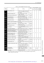
Page 284: ...rted by II series SERVOPACK N A A 10 Overcurrent or Heat Sink Over heated An overcurrent flowed through the IGBT Heat sink of SERVOPACK was over heated N A L H H H A 30 Regeneration Error Detected Reg...

Page 285: ...Encoder Clear Error and Multiturn Limit Setting Error The multiturn for the absolute encoder was not properly cleared or set N A A C9 Encoder Communications Error Communications between SERVO PACK and...

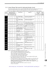
Page 286: ...g in Pn51E H H H A 91 Overload This warning occurs before the overload alarms A 71 or A 72 occur If the warning is ignored and operation con tinues an overload alarm may occur L H H A 92 Regenerative...

Page 287: ...pplication Module which Detects Alarms Alarm Name Meaning Alarm Code Output Servo Alarm ALM Output NS 100 NS 115 NS 300 NS 500 FC 100 ALO 1 ALO 2 ALO 3 A C6 Fully Closed Encoder Phase A B Disconnectio...

Page 288: ...nected or the communications are being sent or from SigmaWin and another device a personal computer the following MECHATROLINK II commands can not be carried out unconditionally command warning A 95 a...

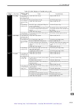
Page 289: ...The SERVOPACK and servomotor capacities do not correspond to each other Servomotor capacity SERVOPACK capacity 1 4 or servomotor capacity SERVOPACK capacity 4 Select the proper combination of SERVOPAC...

Page 290: ...ck for incorrect wiring and disconnection of the regenerative resistor Correct the wiring for the regenerative resistor The regenerative resistor is disconnected Reconsider the load and operation cond...

Page 291: ...OFF or replace the SERVO PACK A SERVOPACK fault occurred Replace the SERVOPACK Occurred during normal operation The AC power supply voltage was lowered and large voltage drop occurred Check the AC pow...

Page 292: ...OFF A SERVOPACK fault occurred Replace the SERVOPACK Occurred when the servomotor was running in servo OFF status The rotating energy at a DB stop exceeds the DB resistance capacity cReduce the motor...

Page 293: ...red in the encoder Turn the encoder power supply OFF and then ON again If this alarm occurs frequently replace the servomotor A SERVOPACK fault occurred Replace the SERVOPACK Occurred during normal op...

Page 294: ...tor A SERVOPACK fault occurred Replace the SERVOPACK A C8 Absolute Encoder Clear Error and Multi turn Limit Set ting Error Occurred when the control power sup ply was turned ON An encoder fault occurr...

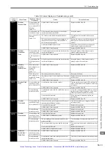
Page 295: ...RVOPACK The servomotor did not run with posi tion reference input Wirings of the servomotor U V and W are incorrect Correct the servomotor wiring A SERVOPACK fault occurred Replace the SERVOPACK Norma...

Page 296: ...erator with the power supply was turned ON The contact between the digital operator and the SERVOPACK is faulty Insert securely the connector or replace the cable The external noise interference occur...

Page 297: ...ncorrect and the contact is faulty Correct the encoder wiring or confirm that the connector is inserted securely The starting torque exceeds the maximum torque Reconsider the load and operation condi...

Page 298: ...ror clear counter CLR input is turned ON Check CLR input pins Turn CLR input signal OFF The forward run prohibited P OT or reverse run prohibited N OT input signal is turned OFF Check P OT or N OT inp...

Page 299: ...ical potential varies by influence of such machines on the servomotor side as welders Check if the machine is correctly grounded Ground the machine separately from PG side FG SERVOPACK pulse counting...

Page 300: ...if the overtravel limit switch SW operates properly Correct the overtravel limit SW Check if the overtravel limit switch SW is connected correctly Correct the overtravel limit SW wiring The overtravel...

Page 301: ...s the recommended specifications Use input signal cable with the specified specifications Noise interference because the input signal cable distance is too long The wiring distance must be 3 m max and...

Page 302: ...or Inspections Item Frequency Procedure Comments Vibration and Noise Daily Touch and listen Levels higher than normal Exterior According to degree of contamination Clean with cloth or compressed air I...

Page 303: ...whether the parts should be replaced or not The parameters of any SERVOPACKs overhauled by Yaskawa are reset to the factory settings before ship ping Be sure to confirm that the parameters are proper...

Page 304: ...Example of Connection to OMRON s Motion Control Unit 11 9 11 2 4 Example of Connection to OMRON s Position Control Unit 11 10 11 2 5 Example of Connection to MITSUBISHI s AD72 Positioning Unit SERVOP...

Page 305: ...ime tm 1 2 s max Ball screw diameter DB 0 04 m Friction coefficient 0 2 Ball screw lead PB 0 01 m Mechanical efficiency 0 9 90 Coupling mass MC 1 kg Coupling outer diameter DC 0 06 m 1 Ball screw Serv...

Page 306: ...e 13 8 N m Servomotor moment of inertia 13 9 10 4 kg m2 SERVOPACK allowable load moment of inertia 69 58 10 4 kg m2 8 Verification on the Provisionally Selected Servomotor Required starting torque Req...

Page 307: ...ing distance 0 25 m Ball screw length LB 0 8 m Positioning time tm Less than 1 2 s Ball screw diameter DB 0 016 m Electrical stop accuracy 0 01 mm Ball screw lead PB 0 005 m Friction coefficient 0 2 C...

Page 308: ...SERVOPACK b Specifications of Servomotor and SERVOPACK Rated output 200 W Rated motor speed 3000 min 1 Rated torque 0 637 N m Instantaneous peak torque 1 91 N m Servomotor rotor moment of inertia 0 2...

Page 309: ...oop gain Kp 30 1 S 12 Electrical Stop Accuracy The above results confirm that the selected SERVOPACK and servomotor are applicable for the position control T T 0 139 60ta 60 0 1 2 N J J 2 3000 0 209 1...

Page 310: ...9 ALM 32 CN1 CN2 C SEL Control mode switch 41 CN1 SVA 01 P OT 42 24V IN 47 ALM 31 ZERO HOME LS input P OT input N OT input EXT DEC input TGON BRK 28 SG 10 SEN 4 BAT 22 BAT 21 PB 35 PB 36 SG 1 TGON BRK...

Page 311: ...17 31 2 23 24 20 6 43 42 41 47 4 27 32 30 10 29 31 5 2 33 34 35 36 19 44 21 22 40 NREF SG PA PAL PB PBL PC PCL SG 24V OUT SVON ALMRST PCON OTR OTF DOSEN 0V SEN SG 0V 0V SVALM 0V SVRDY BRK BAT 0BAT V...

Page 312: ...t I O connec tor section must be short circuited at the connector 7 Make the setting so that the servo can be turned ON OFF by the S ON signal CN2 CN1 3 4 5 16 8 9 13 12 11 19 15 14 18 1 5 6 1 19 20 3...

Page 313: ...12 7 14 15 W V A 1 B 2 C 3 D 4 U Position control unit Servomotor SGDM SGDH SERVOPACK CS1W NC133 233 433 manufactured by OMRON A16 A11 A14 A1 A2 A8 A20 A22 A23 A21 A19 11 SIGN CLR CLR PCO PULS PULS SI...

Page 314: ...licable to Mitsubishi s AD72 Positioning Unit and Yaskawa s SGDM SGDH SERVOPACK are shown in the diagram 43 42 1Ry 24V I O power supply 0 24 V 24 V CONT SERVO CN1 ENCO CN1 STOP DOG SV ON READY PULSE A...

Page 315: ...s applicable to Mitsubishi s AD75 Positioning Unit and Yaskawa s SGDM SGDH SERVOPACK are shown in the diagram 24V 024V 1Ry CN1 CN1 STOP DOG READY PGO PULSE SIGN CLEAR 1Ry 2 2K 19 14 15 12 8 7 32 31 20...

Page 316: ...tuning of analog speed torque reference offset Fn00A Manual adjustment of speed reference offset Fn00B Manual adjustment of torque reference offset Fn00C Manual zero adjustment of analog monitor outpu...

Page 317: ...The following explains the purpose of each digit of a parameter Pn000 0 or n Indicates the value for the 1st digit of parameter Pn000 Pn000 1 or n Indicates the value for the 2nd digit of parameter P...

Page 318: ...Internally set speed control contact reference Position control pulse train reference Internally set speed control contact reference Torque control analog reference Position control pulse train refere...

Page 319: ...ction 0 1 ALO1 ALO2 and ALO3 output only alarm codes Warning Code Output Selection 4th digit 3rd digit 2nd digit 1st digit n Applicable to main circuit DC power input Input DC power supply between 1 a...

Page 320: ...Loop Gain 1 to 2000 1 s 40 Immediately Pn107 Bias 0 to 450 1 min 1 0 Immediately Pn108 Bias Width Addition 0 to 250 1 reference unit 7 Immediately Pn109 Feed forward 0 to 100 1 0 Immediately 0 1 2 3 4...

Page 321: ...Level setting Pn10E Uses position error pulse as the condition Level setting Pn10F No mode switch function available PI control IP control Reserved Do not change Immediately Immediately Immediately Im...

Page 322: ...ack Compensation 1 2 1 to 500 1 100 Immediately Pn112 Reserved Do not change 100 Pn113 1000 Pn114 200 Pn115 32 Pn116 16 Pn117 100 Pn118 100 Pn119 50 Pn11A 1000 Pn11B 50 Pn11C 70 Pn11D 100 Pn11E 100 Pn...

Page 323: ...tive logic Phase A Phase B 1 positive logic Phase A Phase B 2 positive logic Phase A Phase B 4 positive logic Sign Pulse negative logic CW CCW negative logic Phase A Phase B 1 negative logic Phase A P...

Page 324: ...iately Pn302 Internal Set Speed 2 0 to 10000 1 min 1 200 Immediately Pn303 Internal Set Speed 3 0 to 10000 1 min 1 300 Immediately 0 1 Acceleration deceleration filter Average movement filter Reserved...

Page 325: ...equency 50 to 2000 1 Hz 2000 Immediately Pn40A First Stage Notch Filter Q Value 50 to 400 0 01 70 Immediately Pn40B Second Stage Notch Filter Frequency 50 to 2000 1 Hz 2000 Immediately Pn40C Second St...

Page 326: ...N P CON Signal Mapping P control when ON L level 4th digit 3rd digit 2nd digit 1st digit n C D E F Uses the sequence input signal terminals with standard allocation Changes the sequence input signal a...

Page 327: ...F H level Reverse run allowed when CN1 45 input signal is OFF H level Reverse run allowed when CN1 46 input signal is OFF H level C D E F P CL Signal Mapping Forward Torque Limit when ON L level 0 to...

Page 328: ...s ON L level Sets signal ON Sets signal OFF ON when CN1 40 input signal is OFF H level ON when CN1 41 input signal is OFF H level ON when CN1 42 input signal is OFF H level ON when CN1 43 input signal...

Page 329: ...t signal is OFF H level ON when CN1 46 input signal is OFF H level ON when CN1 46 input signal is ON L level ZCLAMP Signal Mapping Zero clamp when ON L level INHIBIT Signal Mapping Reference pulse inh...

Page 330: ...to 3 0 to 3 Warning Signal Mapping WARN 0 1 2 3 Disabled the above signal is not used Outputs the signal from CN1 25 or 26 terminals Outputs the signal from CN1 27 or 28 terminals Outputs the signal...

Page 331: ...3 ON when CN1 40 input signal is ON L level ON when CN1 41 input signal is ON L level ON when CN1 42 input signal is ON L level ON when CN1 43 input signal is ON L level ON when CN1 44 input signal i...

Page 332: ...Immediately Pn109 0 Feed forward Immediately Pn10A 0 00 ms Feed forward Filter Time Constant Immediately Pn10B 0000 Gain related Application Switches After restart Immediately Pn10C 200 Mode Switch To...

Page 333: ...ediately Pn303 300 min 1 Internal Set Speed 3 Immediately Pn304 500 min 1 JOG Speed Immediately Pn305 0 ms Soft Start Acceleration Time Immediately Pn306 0 ms Soft Start Deceleration Time Immediately...

Page 334: ...r restart Pn50D 8888 Input Signal Selections 4 After restart Pn50E 3211 Output Signal Selections 1 After restart Pn50F 0000 Output Signal Selections 2 After restart Pn510 0000 Output Signal Selections...

Page 335: ...rm selection 8 50 CLR 6 12 CLT 6 13 CN1terminal layout 6 11 CN2 terminal layout 6 9 COIN 6 13 connecting the servomotor power lines 3 11 connection cable for digital operator 2 7 connection to host co...

Page 336: ...uency 9 18 second stage notch filter Q value 9 18 O online autotuning functions 9 2 operating using position control 8 49 operating using speed control with an internally set speed 8 68 operating usin...

Page 337: ...ies 4 11 precautions on installation 4 5 ratings and specifications 4 2 wire size 5 2 SERVOPACK inspection 10 20 SERVOPACK s parts replacement schedule 10 21 setting a reference pulse form 8 49 settin...

Page 338: ...lation 4 3 voltage resistance test 4 6 V REF 6 12 W WARN 6 13 8 78 warning code output 10 4 warning display 10 4 warning display and troubleshooting 10 15 warning output WARN 8 78 wiring encoders 6 8...

Page 339: ...the back cover Date of Publication Rev No Section Revised Content August 2008 First edition Published in Japan August 2008 08 8 MANUAL NO SIEP S800000 59A Date of publication Date of original publica...

Page 340: ...SKAWA ELETRICO DO BRASIL LTDA Avenida Fagundes Filho 620 Sao Paulo SP CEP 04304 000 Brazil Phone 55 11 3585 1100 Fax 55 11 5581 8795 YASKAWA ELECTRIC EUROPE GmbH Hauptstra e 185 65760 Eschborn Germany...

Page 341: ...uipment Have surplus equipment taking up shelf space We ll give it a new home Learn more Visit us at artisantg com for more info on price quotes drivers technical specifications manuals and documentat...

Reviews: