5.7 Absolute Encoders
5 -97
5.
When “PGCL5” is displayed, press the MODE/SET Key. The display will change as fol-
lows, and the absolute encoder’s multi-turn data will be cleared.
Flashes for
1 second.
6.
Press the DATA/SHIFT Key to return to the auxiliary function mode.
This completes the absolute encoder’s setup operation. Turn the power OFF and then back ON
again.
If the following absolute encoder alarms are displayed, the alarms must be cleared using the method described
above for the setup operation. They cannot be cleared by the Servopack’s alarm reset (/ARM-RST) input signal.
S
Encoder backup alarm (A.81)
S
Encoder sum check alarm (A.82)
In addition, if a monitoring alarm is generated in the encoder, the alarm must be cleared by turning OFF the
power.
5.7.5 Absolute Encoder Reception Sequence
The sequence in which the Servopack receives outputs from the absolute encoder and transmits
them to the host device is shown below.
Be sure you understand this section when designing the host device.
J
J
Outline of Absolute Signals
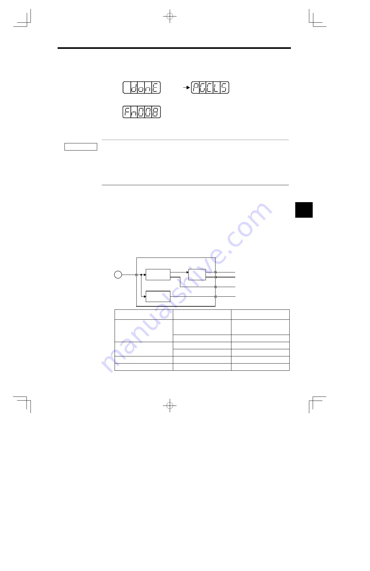
The absolute encoder’s outputs are PAO, PBO, PCO, and PSO signals as shown below.
PG
Servopack
Serial data
®
pulse conversion
PS
PAO
PBO
PCO
PSO
Dividing
circuit
(Pn201)
Data
®
data
conversion
Signal Name
Status
Signal Contents
PAO
Initial state
Serial data
Initial incremental pulse
Normal state
Incremental pulse
PBO
Initial state
Initial incremental pulse
Normal state
Incremental pulse
PCO
Normal state
Origin pulse
PSO
Normal state
Rotation count serial data
5
IMPORTANT
AUDIN - 7 bis rue de Tinqueux - 51100 Reims - France - Tel : 03.26.04.20.21 - Fax : 03.26.04.28.20 - Web : http: www.audin.fr - Email : info@audin.fr


