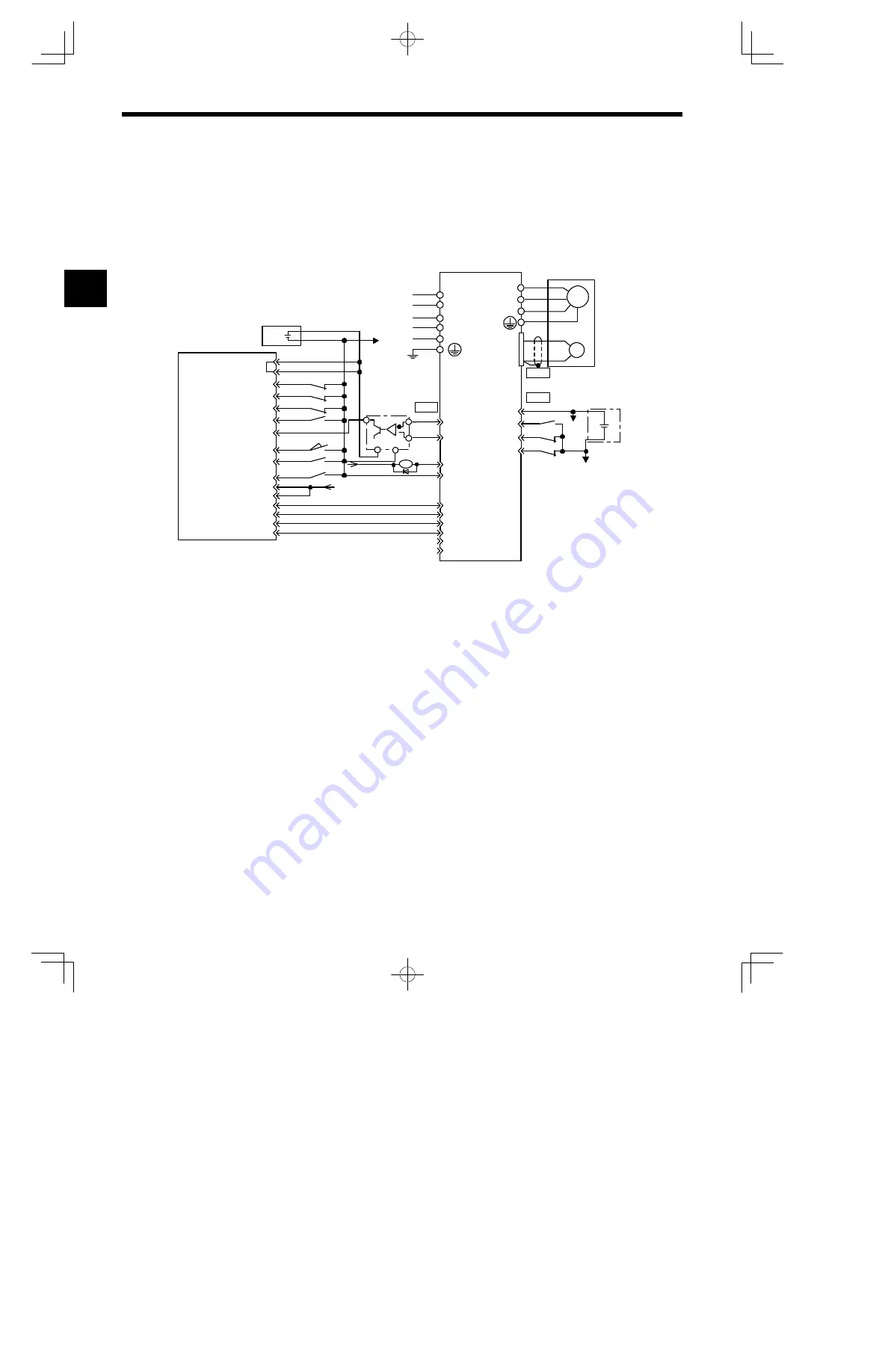
Host Controller Connection Examples
A -6
A.5 Connecting OMRON’s C500-NC112 Position Control Unit
The following diagram showsan example of connecting to the OMRONC500-NC112 Position Con-
trol Unit. In this example, the Servopack is used in the position control mode.
4Ry
3Ry
47
43
42
40
8 7
9 20
10 19
4Ry
3Ry
1Ry
4B *4
+12V
PULSE OUTPUT
10B
10A
CN1
CN2
+--
+12V
I/O Power Supply
C500-NC112
(Made by OMRON)
CW LIMIT
CCW LIMIT
EMERGENCY STOP
ORIGIN
ORIGIN PROXIMITY
LOCAL
READY
+5V
1A
4A
3B
3A
2B
2A
1B
9B
9A
8B
8A
5B
5A
+5 V
+24V
12V
*
1
6 LRX-01/A2
*3
0
12
V
+24VIN
P-OT
N-OT
/S-ON
31
32
15
12
11
8
7
14
+24 V
1Ry
CN1
0V
EXTERNAL
INTERRUPT
Servopack
SGDH
L1C
L3
L2
L1
L2C
PC
O
/PCO
ALM+
ALM--
PULSE
CLR
SIGN
/PULSE
/CLR
/SIGN
0
12
V
M
PG
W
V
U
A (1)
B (2)
C (3)
D (4)
Servomotor
* 1.
The ALM signal is output for approximately two seconds when the power is turned ON. Take this into consider-
ation when designing the power ON sequence. The ALM signal actuates the alarm detection relay 1Ry to stop
main circuit power supply to Servopack.
* 2.
Set user constant Pn200.0 to “1”.
* 3.
Manufactured by Yaskawa Controls Co., Ltd.
Note
Only signals applicable to OMRON’s C500-NC112 Position Control Unit and Yaskawa’s SGDH Servopack
are shown here.
*2
External
power
supply
+24 V
A
AUDIN - 7 bis rue de Tinqueux - 51100 Reims - France - Tel : 03.26.04.20.21 - Fax : 03.26.04.28.20 - Web : http: www.audin.fr - Email : info@audin.fr


