7 Alarm and Warning Processing
7.6.4 Using the SERVOPACK to Perform Emergency Stop Processing and the Power Regeneration Converter to Turn OFF the Main Circuit
7-20
7.6.4
Using the SERVOPACK to Perform Emergency Stop Processing and the
Power Regeneration Converter to Turn OFF the Main Circuit
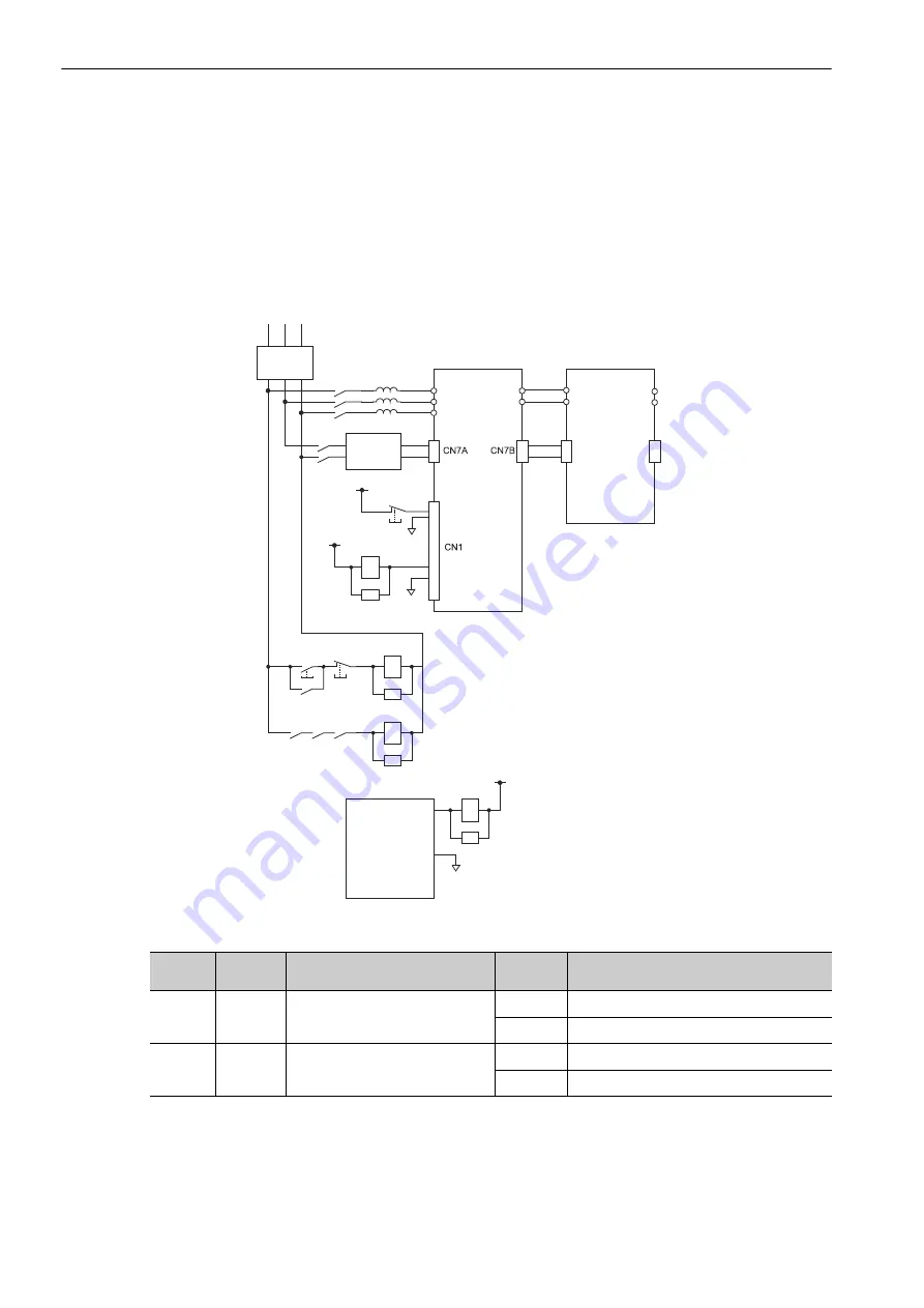
Perform the following wiring to use the SERVOPACK to perform emergency stop processing.
Connect the emergency stop switch to the power regeneration converter’s CN1 connector (/ESP+ and
/ESP-).
The SERVOPACK performs axis stop processing.
Main circuit magnetic contactor (2KM) control is performed with the output signal from the power regenera-
tion converter’s CN1 connector (/MCON+ and /MCON-).
(1) Signal Wiring and Related Parameters
When the SERVOPACK is used to perform emergency stop processing and the power regeneration converter
is used to control the main circuit magnetic contactor, set the parameters described in (1) to (6) in
7.6.1 Emer-
gency Stop and Main Circuit Magnetic Contactor Control Settings
.
CACP-JU
3A
CACR-JU
2A
R S T
P
N
P
N
P
N
CN7A
CN7B
24 V
0 V
2Ry
24 V
ALM+
0 V
ALM-
1KM
2KM
OFF
ON
1KM
1KM 1Ry 2Ry
2KM
1KM
1Ry
24 V
0 V
Controller
Emergency
stop
Control
power supply
(24 VDC)
SERVOPACK
Converter
AC reactors
Filter
Type
Signal
Name
Power Regeneration Converter
Connector Pin Numbers
Setting
Meaning
Input
/ESP+
/ESP-
CN1-11, CN1-12
ON
Emergency stop released (normal operation).
OFF
Emergency stop
Output
/MCON+
/MCON-
CN1-1, CN1-2
ON
Main circuit turned ON (normal operation).
OFF
Main circuit turned OFF.


