Programming 5 - 37
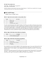
b5-29 PI Square Root Gain
Setting Range:
0.00 to 2.00
Factory Default: 1.00
A multiplier applied to the square root of the feedback.
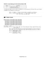
b5-30 PI Output Square Root Monitor Selection
If the PI Function is regulating the flow of a closed loop system by using a pressure feedback, it may be convenient to view the
square root of the PI output using monitor U1-37.
b8 Energy Savings
The energy savings function improves overall system operating efficiency by operating the motor at its highest efficiency. This
is accomplished by continuously monitoring the motor load and adjusting the motor terminal voltage so that the motor always
operates near its rated slip frequency. A motor is most efficient when operating near rated slip conditions.
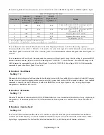
b8-01 Energy Savings Selection
When the Energy Savings function is enabled (b8-01= “1: Enabled”), the Drive reduces the output voltage to the motor below
the voltage value specified by the programmed V/f pattern whenever the motor load is light. Since torque is reduced during
this voltage reduction, the voltage has to return to normal levels when the load returns. The energy savings is realized through
improved motor efficiency. The reduced output voltage causes increased rotor slipping even with a light load. A motor is most
efficient when operating fully loaded (i.e. operating at rated slip).
b8-04 Energy Saving Coefficient Value
Setting Range:
0.0 to 655.0
Factory Default: Model Dependent
Parameter b8-04 is used in maximizing motor efficiency. The factory setting will be Drive capacity dependent but can be
adjusted in small amounts while viewing the kW monitor (U1-08) and running the Drive to minimize the output kW. A larger
value typically results in less voltage to the motor and less energy consumption. Too large a value will cause the motor to stall.
Setting
Description
0
Disabled (
factory default
)
1
Enabled
Setting
Description
0
Disabled (
factory default
)
1
Enabled
Summary of Contents for E7LBA002
Page 1: ...E7L Drive Bypass Technical Manual Model E7L Document Number TM E7L 01 ...
Page 8: ...Introduction vi Notes ...
Page 12: ...Table of Contents x Notes ...
Page 54: ...Electrical Installation 2 22 Wiring Diagram ...
Page 55: ...Electrical Installation 2 23 ...
Page 87: ...Start Up and Operation 4 9 Notes ...
Page 202: ...Diagnostic Troubleshooting 6 30 Notes ...
Page 248: ...Capacity Related Parameters B 6 Notes ...
Page 279: ...Communications D 27 Note ...
Page 280: ...Communications D 28 ...
Page 292: ...Spare Parts F 6 ...
Page 304: ...Index 12 ...
Page 305: ......


