Programming 5 - 42
d3 Jump Frequencies
d3-01 Jump Frequency 1
d3-02 Jump Frequency 2
d3-03 Jump Frequency 3
Setting Range:
0.0 to 200.0 Hz
Factory Default: 0.0 Hz
d3-04 Jump Frequency Width
Setting Range:
0.0 to 20.0 Hz
Factory Default: 1.0 Hz
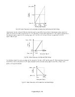
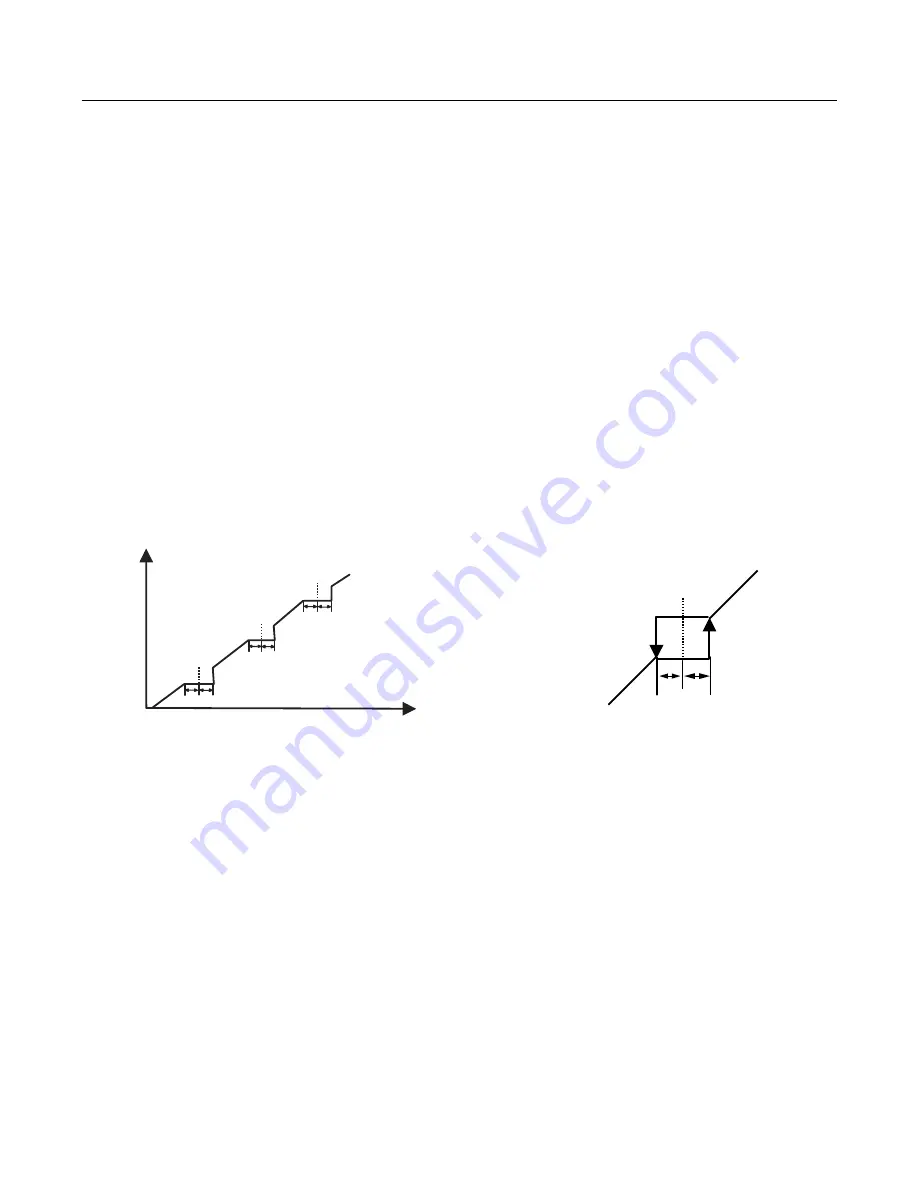
In order to avoid continuous operation at a speed that causes resonance in driven machinery, the Drive can be programmed
with jump frequencies that will not allow continued operation within specific frequency ranges. If a speed is commanded that
falls within a dead band, or Jump Frequency, the Drive will clamp the frequency reference just below the dead band and only
accept higher speed commands when the commanded speed rises above the upper end of the dead band, for increasing
references. Similarly, the Drive will clamp the frequency reference just above the dead band and only accept lower speed
commands when the command speed falls below the lower end of the dead band, for decreasing references.
Fig 5.22 Jump Frequency Characteristics
Setting the center point of the dead band with the d3-01 through d3-03 parameters and setting the width of the dead band with
parameter d3-04 determines the dead band characteristics. The programmer can set up to three Jump Frequencies. If multiple
Jump Frequencies are programmed the following rule applies:
d3-01
< =
d3-02
<
=
d3-03
d3-03
d3-04
User Speed
Command Input
Accepted Speed
Command
d3-01
d3-02
d3-04
d3-04
d3-03
d3-04
Summary of Contents for E7LBA002
Page 1: ...E7L Drive Bypass Technical Manual Model E7L Document Number TM E7L 01 ...
Page 8: ...Introduction vi Notes ...
Page 12: ...Table of Contents x Notes ...
Page 54: ...Electrical Installation 2 22 Wiring Diagram ...
Page 55: ...Electrical Installation 2 23 ...
Page 87: ...Start Up and Operation 4 9 Notes ...
Page 202: ...Diagnostic Troubleshooting 6 30 Notes ...
Page 248: ...Capacity Related Parameters B 6 Notes ...
Page 279: ...Communications D 27 Note ...
Page 280: ...Communications D 28 ...
Page 292: ...Spare Parts F 6 ...
Page 304: ...Index 12 ...
Page 305: ......


