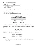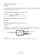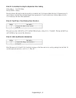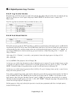
Programming 5 - 71
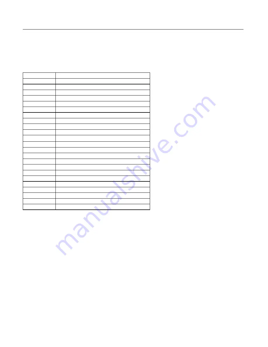
o1 Monitor Configuration
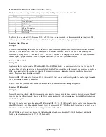
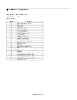
o1-01 User Monitor Selection
Setting Range:
6 to 53
Factory Default: 6
Setting
Description
6
Output Voltage (
factory default
)
7
DC Bus Voltage
8
Output Power
10
Input Terminal Status
11
Output Terminal Status
12
Drive Operation Status
13
Cumulative Operation Time
14
Software Number
15
Terminal A1 Input Voltage
16
Terminal A2 Input Voltage
18
Motor Secondary Current (I
q
)
20
Output Frequency After Soft Start
24
PI Feedback Value
28
CPU Number
34
First Parameter Causing an OPE
36
PI Input
37
PI Output
38
PI Setpoint
39
Memobus Communication Error Code
40
Heatsink Cooling Fan Operation Time
51
Auto Mode Frequency Reference Value
52
Hand Mode Frequency Reference Value
53
PI Feedback 2 Value
Summary of Contents for E7LBA002
Page 1: ...E7L Drive Bypass Technical Manual Model E7L Document Number TM E7L 01 ...
Page 8: ...Introduction vi Notes ...
Page 12: ...Table of Contents x Notes ...
Page 54: ...Electrical Installation 2 22 Wiring Diagram ...
Page 55: ...Electrical Installation 2 23 ...
Page 87: ...Start Up and Operation 4 9 Notes ...
Page 202: ...Diagnostic Troubleshooting 6 30 Notes ...
Page 248: ...Capacity Related Parameters B 6 Notes ...
Page 279: ...Communications D 27 Note ...
Page 280: ...Communications D 28 ...
Page 292: ...Spare Parts F 6 ...
Page 304: ...Index 12 ...
Page 305: ......

