Programming 5 - 74
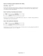
o1-05 LCD Contrast Adjustment
Setting Range:
0 to 5
Factory Default: 3
The contrast setting of the LCD display of the digital operator can be adjusted by the setting of parameter o1-05. The higher the
number programmed into o1-05, the darker the background will become. Set o1-05 to the value that makes the LCD the easiest to
view at the normal viewing distance and angle.
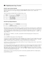
o1-06 User Monitor Selection Mode
(Optional LCD Operator only)
o1-07 Second Line User Monitor
(Optional LCD Operator only)
Setting Range:
1 to 53
Factory Default: 2
o1-08 Third Line User Monitor
(Optional LCD Operator only)
Setting Range:
1 to 53
Factory Default: 3
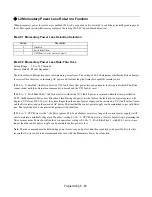
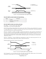
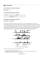
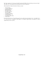
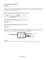
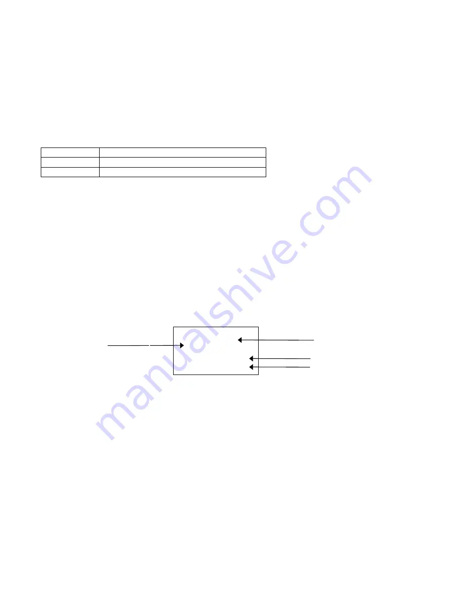
Normally the monitors shown directly below the active monitor are the next two sequential monitors. If o1-06 (User Monitor
Selection Mode) is set to “1: 3 Mon Selectable”, those two monitors are locked as specified by parameters o1-07 and o1-08 and
will not change as the top parameter is scrolled with the INCREASE and DECREASE keys.
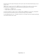
For Example:
The Display above showing PI Feedback, PI Output and PI Setpoint would be useful when setting up a PI Control Loop.
Setting
Description
0
3 Mon Sequential (
factory default
)
1
3 Mon Selectable
-DRIVE- Rdy
PI Feedback
U1-24= 64.55%
- - - - - - - - - - - - - - - - - - - - - - - - - - - - -
U1-37= 0.00%
U1-38= 2.50%
Active Monitor
o1-07
o1-08
Active Monitor Title
PI Output
PI Setpoint
o1-07=37
o1-08=38
Optional LCD Operator
Summary of Contents for E7LBA002
Page 1: ...E7L Drive Bypass Technical Manual Model E7L Document Number TM E7L 01 ...
Page 8: ...Introduction vi Notes ...
Page 12: ...Table of Contents x Notes ...
Page 54: ...Electrical Installation 2 22 Wiring Diagram ...
Page 55: ...Electrical Installation 2 23 ...
Page 87: ...Start Up and Operation 4 9 Notes ...
Page 202: ...Diagnostic Troubleshooting 6 30 Notes ...
Page 248: ...Capacity Related Parameters B 6 Notes ...
Page 279: ...Communications D 27 Note ...
Page 280: ...Communications D 28 ...
Page 292: ...Spare Parts F 6 ...
Page 304: ...Index 12 ...
Page 305: ......

