Index - 8
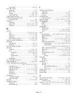
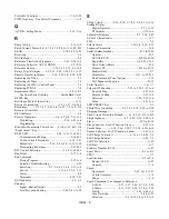
Monitor Select (o1-01 - o1-08) .................... A-23, A-24
MOP/Trim Control (d4-01 - d4-02) ......................... A-9
Motor Overload (L1-01 - L1-05) ........................... A-19
Motor Setup (E2-01 - E2-05) ..................................A-11
Option Dependent Settings .............................. 5-6, 5-25
PI Control (b5-01 - b5-30) ............................... A-5, A-6
Preset Reference (Speeds) (d1-01 - d1-17) .............. A-8
Programming (Basic) ....................................5-1 to 5-80
PwrLoss Ridethru (L2-01 - L2-05) ........................ A-19
Ref Detection (L4-01 - L4-06)............................... A-21
Reference Limits (d2-01 - d2-03) ............................ A-9
S-Curve Acc/Dec (C2-01 - C2-02) .......................... A-7
Sequence (b1-01 - b1-12)......................................... A-4
Serial Com Setup (H5-01 - H5-09) ........................ A-18
Setting and Reading .................................... 3-11 to 3-22
Speed Search (b3-01 - b3-14) .................................. A-5
Stall Prevention (L3-01 - L3-06)............................ A-20
Torque Comp (C4-01 - C4-02)................................. A-8
Torque Detection (L6-01 - L6-03) ......................... A-21
Troubleshooting ...................................................... 6-16
User (A2-01 - A2-32)....................................... A-2, A-3
V/f Pattern (E1-01 - E1-13).................................... A-10
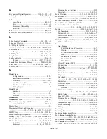
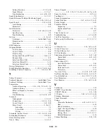
Parity - See Modbus Communications............................ D-3
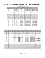
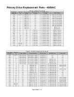
Parts, Replacement ........................... F-1, Inside Back Cover
Password
Setting ............................................................. 5-11, A-2
Troubleshooting ...................................................... 6-19
PCB ................................................................................ 2-24
Bypass Operator Control Panel (A3) ..............................
.......................................... 1-12, 1-13, 6-2, 7-2, 7-4, F-5
Bypass Controller Logic (A2).........................................
...... 1-12 to 1-15, 2-8, 2-11, 2-18, 6-2, 6-5, 7-2, 7-4, F-5
Drive Control ............................................. 7-2, F-2, F-3
Drive Gate Drive ........................................ 7-2, F-2, F-3
Drive Power ............................................... 7-2, F-2, F-3
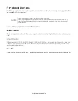
Peripheral Devices
Semiconductor Fuses ................................................E-4
Short Circuit Protection Criteria ...............................E-2
Troubleshooting ...................................................... 6-22
Phase Loss Detection
And Auto Restart..................................................... 5-66
Input ...................................................... 6-11, A-22, B-3
Phase-to-Phase Short...................................................... 6-10
Physical Installation -See Installation, Physical............... 1-1
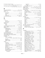
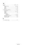
PI Function
Accel/Decel Time............................................ 5-33, A-6
Block Diagram ........................................................ 5-23
Feedback ............................ 5-23 to 5-32, 6-9, 6-14, A-6
Differential ............................................. 5-57, A-16
Loss Detection ......................................... 5-32, A-6
Reference Missing Detection ................... 5-31, A-5
Square Root Activation............................ 5-36, A-6
Integral Limit Setting ...................................... 5-30, A-5
Integral Time Setting....................................... 5-29, A-5
Offset Adjustment ........................................... 5-30, A-5
Output ..............................................................5-30, A-5
Gain Setting ..............................................5-31, A-5
Level Selection .........................................5-31, A-5
Limit .........................................................5-30, A-5
Primary Delay Time Constant ..................5-31, A-5
Square Root Monitor ................................5-37, A-6
Parameters .................................. 5-23 to 5-37, A-5, A-6
Option Dependent Settings...............................5-25
Proportional Gain (PI) ....................................5-29, A-5
Setpoint ......................................5-23 to 5-29, 5-33, A-6
Boost Setting ............................................5-35, A-6
Display Scaling.........................................5-33, A-6
Selection ......................................... 5-25, 5-33, A-6
Value .........................................................5-33, A-6
Sleep
Delay Time ...............................................5-32, A-6
Function............................................................5-32
Function Start Level .................................5-32, A-6
Input Source .............................................5-34, A-6
Snooze
Deactivation Level ...................................5-35, A-6
Delay Time ...............................................5-35, A-6
Feedback Level.........................................5-36, A-6
Function............................................................5-35
Level .........................................................5-36, A-6
Maximum Boost Time..............................5-36, A-6
Square Root Gain.............................................5-37, A-6
PI Mode...................................................................5-23, A-5
PI Monitors
Feedback (U1-24) ..........................................5-33, A-27
Output (U1-37) ..............................................5-32, A-27
Setpoint (U1-38) ............................................5-33, A-27
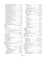
PLC (Programmable Logic Controller) ........................... D-4
Plenum Rated ..................................................................1-19
Pneumatic Input ......................................1-8, 5-6, 5-25, 5-58
Potentiometer (Connection) .................................... 2-12, 5-7
Power
Connection............................................. 1-12, 2-2 to 2-7
Energy Saving..........................................5-37, A-7, B-3
Output, +15Vdc .................................... 2-12, 2-18, 2-20
Loss Ride-thru ...............................5-60, A-19, B-3, C-4
Module Spare Parts............................................ F-2, F-3
PCB.............................................................7-2, F-2, F-3
Supply Specifications ....................................... C-2, C-3
Power Factor Correction Capacitors......................6-11, 6-15
Power Up Mode ............................................... 2-17, 4-2, 4-3
Pre-Operation Considerations.................i to iv; 1-1, 2-1, 4-1
Preset Speeds ................................................................... A-8
Preventive Maintenance....................................................7-1
Programming
Basic ............................................................. 5-1 to 5-80
Error (OPE)..............................................................6-16
Menu ........................................................... 3-11 to 3-22
Option Dependent Parameters ........................ 5-3 to 5-9
PI Control Parameters................................. 5-24 to 5-37
Summary of Contents for E7LBA002
Page 1: ...E7L Drive Bypass Technical Manual Model E7L Document Number TM E7L 01 ...
Page 8: ...Introduction vi Notes ...
Page 12: ...Table of Contents x Notes ...
Page 54: ...Electrical Installation 2 22 Wiring Diagram ...
Page 55: ...Electrical Installation 2 23 ...
Page 87: ...Start Up and Operation 4 9 Notes ...
Page 202: ...Diagnostic Troubleshooting 6 30 Notes ...
Page 248: ...Capacity Related Parameters B 6 Notes ...
Page 279: ...Communications D 27 Note ...
Page 280: ...Communications D 28 ...
Page 292: ...Spare Parts F 6 ...
Page 304: ...Index 12 ...
Page 305: ......

