Allowable load for wrist axis and wrist flange
7
-
43
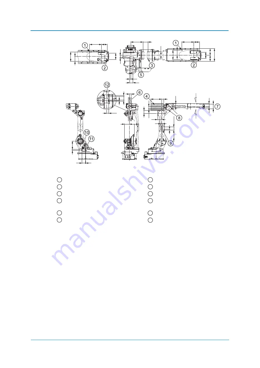
Fig. 7-1: Installing peripheral devices
The mounts marked with „*“ must be used only to secure the cables.
The thread depth for through taps must be 10 mm or less.
4 M6 x 12 threaded holes
Dimension of the casting
4 M5 x 11 threaded holes
2 M5 x 10 threaded holes*
4 M6 x 12 threaded holes
8 M5 through tap*
Center of gravity of accessories mount on
U arm in this range
4 M10 x 18 threaded holes
4 M6 x 14 threaded holes
4 M10 x 12 threaded holes
Mount the peripherals in this range
4 M8 x 16 threaded holes
88
83.5
93.5
177
165
77.5
130
70
100
168
70
15
45
13
26
88
130
70
77.5
165
6
15
48
15
28.5
92
13
229
30
135
255
50
84
59
34
300
60
114
48
30
302
3×30=90
81
48
78
30
128
A
B
1
7
2
8
3
9
4
10
5
11
6
12
Summary of Contents for GP25-12
Page 1: ...ROBOTICS YYR 1 06VXH25 A10 GP25 12 Standard Operating and Maintenance Manual...
Page 51: ...Maintenance and inspection 9 51 Fig 9 2 Inspection intervals...
Page 56: ...Maintenance and inspection 9 56 9 3 Wrist unit Sealing part U arm Cover Gasket U arm 1 2 3...
Page 77: ...Parts lists 11 77...


