I-3
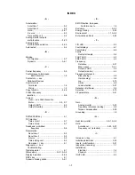
Slip compensation .................................. 5-34
Soft start — see S-curve
Specifications ......................................... A2-1
Speed :
Coincidence ........................................ 5-30
Search ................................................ 5-23
Stall prevention :
Accel ................................................... 5-35
Decel .................................................. 5-35
During running .................................... 5-36
Start-up:
Open loop vector .................................. 2-2
V/f control ............................................. 2-6
STOP/RESET key ........................... 4-1, 5-14
Stopping method selection ..................... 5-37
Switches, internal :
SW1 .................................................... 5-22
SW2 .......................................... 5-10, 5-16
Switching frequency — see
Carrier frequency
- T -
Temperature :
Ambient .............................................. A2-2
Storage .............................................. A2-2
Terminals :
Functions ...................................... 1-4, 1-6
Screw sizes .......................................... 1-3
Thermal overload protection ..................... 5-38
Torque boost (open loop
vector) ............................................ 5-39
Torque compensation
gain (V/F control) ................................ 5-39
Torque detection ..................................... 5-31
Troubleshooting ........................................ 6-1
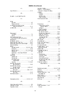
- U -
Up/down function .................................... 5-26
Undertorque detection ............................. 5-58
- V -
V/f pattern ............................................... 5-40
V/f startup procedure ................................ 2-6
Voltage :
DC bus (monitor) .................................. 4-4
DC bus (stall prev.) ............................. 5-35
Max. output ........................................ A2-1
Output (monitor) ................................... 4-4
V/f parameters .................................... 5-41
- W -
Weight ........................................... A5-1, A5-2
Wiring :
2-Wire control ....................................... 1-4
3-Wire control ....................................... 1-4
Auxiliary input and output
power option devices ....................... 1-7
Conduit ..................................................1-7
Control circuit ....................................... 1-5
Diagrams ................................... 1-11, 1-13
Distances ..................... 1-4, 1-5, 1-8, A2-2
Main circuit ........................................... 1-4
INDEX (Continued)
Summary of Contents for GPD315/V7-4X
Page 1: ...GPD 315 V7 and V7 4X Technical Manual...
Page 4: ......
Page 20: ...xvi...
Page 22: ......
Page 40: ...1 18...
Page 52: ...3 2...
Page 56: ...4 4...
Page 101: ...5 45 PID Block Diagram...
Page 130: ...A1 8...
Page 134: ...A3 2...
Page 136: ...A4 2...
Page 146: ...A6 6...
Page 150: ...A7 4...
Page 154: ...A8 4...
Page 158: ......
Page 160: ......


