1-4
Continued
1.3 PHYSICAL INSTALLATION
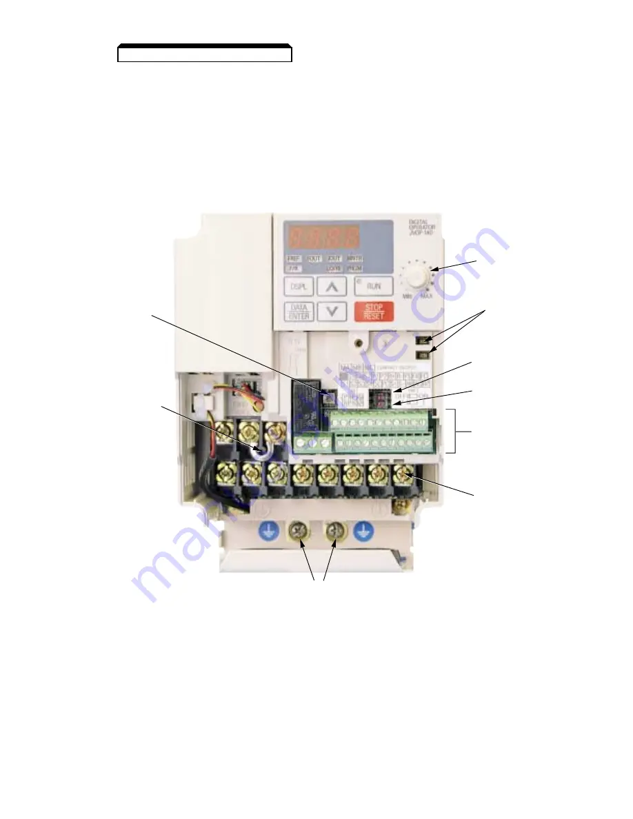
Figure 1-1. Component Identification (Sheet 2 of 3)
Ground Terminal
Main Circuit
Block
Control Circuit
Block
SW2 (2)
Analog Input
Current/Voltage
Selector
SW2 (1)
Terminating
Resistor
for Serial
Communication
Status
Indicator
LEDs
Digital
Operator
Speed Pot
SW1
Digital
Input Type
Shorting
Bar
(Remove
when DC
Reactor
is installed)
Summary of Contents for GPD315/V7-4X
Page 1: ...GPD 315 V7 and V7 4X Technical Manual...
Page 4: ......
Page 20: ...xvi...
Page 22: ......
Page 40: ...1 18...
Page 52: ...3 2...
Page 56: ...4 4...
Page 101: ...5 45 PID Block Diagram...
Page 130: ...A1 8...
Page 134: ...A3 2...
Page 136: ...A4 2...
Page 146: ...A6 6...
Page 150: ...A7 4...
Page 154: ...A8 4...
Page 158: ......
Page 160: ......


