background image


E-6

Operation Precautions

• Select the I/O signal wires for external wiring to connect the product to 

external devices based on the following criteria:

Mechanical strength

Noise interference

Wiring distance

Signal voltage

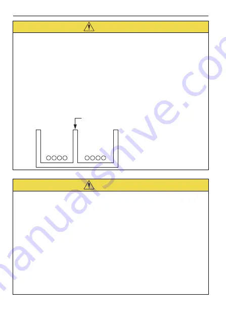
• Separate the I/O signal cables for control circuits from the power 

cables both inside and outside the control panel to reduce the influ-
ence of noise from the power cables.

If the I/O signal lines and power lines are not separated properly, malfunc-
tion may occur.

CAUTION

• Follow the procedures and instructions in the user’s manuals for the 

relevant products to perform normal operation and trial operation.

Operating mistakes while the Servomotor and machine are connected 
may damage the machine or even cause accidents resulting in injury or 
death.

• Implement interlock signals and other safety circuits external to the 

product to ensure safety in the overall system even if the following 
conditions occur.

Product failure or errors caused by external factors

Shutdown of operation due to product detection of an error in self-diag-
nosis and the subsequent turning OFF or holding of output signals

Holding of the ON or OFF status of outputs from the product due to fus-
ing or burning of output relays or damage to output transistors

Voltage drops from overloads or short-circuits in the 24-V output from 
the product and the subsequent inability to output signals

Unexpected outputs due to errors in the power supply, I/O, or memory 
that cannot be detected by the product through self-diagnosis

There is a risk of injury, device damage, or burning.

CAUTION

Example of Separated Cables 

Power cable 

I/O signal  

cables in  

control circuits 

Steel separator 

Summary of Contents for JEPMC-BU3301-E

Page 1: ...STRUCTIONS Unit de Base MP3300 Contr leur de Machine S rie MP3000 INSTRUCTIONS MP3300 MP3000 Model JEPMC BU3301 E BU3302 E BU3303 E BU3304 E Mod le JEPMC BU3301 E BU3302 E BU3303 E BU3304 E JEPMC BU33...

Page 2: ...liability is assumed with respect to the use of the information contained herein Moreover because Yaskawa is constantly striving to improve its high quality products the information contained in this...

Page 3: ...ation marked as shown below is important for safety Always read this information and heed the precautions that are provided DANGER Indicates precautions that if not heeded are likely to result in loss...

Page 4: ...re is a risk of injury Do not approach the machine after a momentary interruption to the power supply When power is restored the product and the device connected to it may start operation suddenly Pro...

Page 5: ...jury Do not overload the product during transportation Follow all instruc tions There is a risk of injury or an accident Never subject the product to an atmosphere containing halogen fluo rine chlorin...

Page 6: ...gen fluo rine chlorine bromine or iodine There is a risk of malfunction or damage Do not step on the product or place heavy objects on the product There is a risk of injury or an accident Do not block...

Page 7: ...pply Refer to the following manual for details on circuits MP3000 Series MP3300 CPU Module Instructions Manual No TOMP C880725 23 If the power supply to the CPU Module is turned ON after the external...

Page 8: ...idents resulting in injury or death Implement interlock signals and other safety circuits external to the product to ensure safety in the overall system even if the following conditions occur Product...

Page 9: ...perate the CPU Module without transferring this data unexpected operation may occur There is a risk of injury or device damage Dispose of the product as general industrial waste Observe all local laws...

Page 10: ...d product in a manner in which it was not originally intended Causes that were not foreseeable with the scientific and technological under standing at the time of shipment from Yaskawa Events for whic...

Page 11: ...p erty Systems that require a high degree of reliability such as systems that sup ply gas water or electricity or systems that operate continuously 24 hours a day Other systems that require a similar...

Page 12: ...llation 13 2 1 Precautions for the Installation Location 13 2 2 Control Panel Cooling Method 14 3 Wiring 16 4 Inspections 17 4 1 Daily Inspections 17 4 2 Periodic Inspections 18 4 3 Replacement Guidel...

Page 13: ...entative immediately 1 1 Nameplate Item Confirmation Method Have you received the correct product as ordered Check the model number on the nameplate on the side of the product Check all acces sories a...

Page 14: ...Manufacturing Year The last two digits of the manufacturing year are given Code Manufacturing Month The manufacturing month is given using the codes listed in the following table Manufacturing Month 1...

Page 15: ...ss temperature increases due to radiant heat or convection from the heat generating object so that the ambient temperature around the product does not exceed 55 C Installation near sources of vibra ti...

Page 16: ...MP3300 at the top of the control panel where the hot air that is generated inside the panel collects Leave sufficient space above and below the MP3300 and maintain ade quate distances from other devi...

Page 17: ...ice is mounted to the airtight panel to circulate the air inside 1 Use the following guideline when selecting the fan 80 80 mm min Maximum air flow 0 9 m3 min Maxi mum static pressure 26 5 Pa or highe...

Page 18: ...3 Wiring E 16 3 Wiring Refer to the following manual for details on connecting the product MP2000 MP3000 Series Machine Controller System Setup Manual Manual No SIEP C880725 00...

Page 19: ...Criteria Correction Installation condition Loose screws or covers All screws and covers must be secure Tighten the screws Connection conditions Loose termi nal screws Screws must not be loose Tighten...

Page 20: ...every 6 to 12 months Measure the tem perature and humid ity with a hydrometer and thermometer and measure corro sive gas They must be within specifica tions Remove sources of contamination or improve...

Page 21: ...ds that are given in the following table Yaskawa will inspect your product and determine if part replacement is required Yaskawa will initialize the settings of all parameters to the default values in...

Page 22: ...confirm EMC standard compliance for the overall machine or equipment 6 UL Standard Compliance The product complies with the following UL standards UL508 E184524 The following table shows the product...

Page 23: ...facturing Year and Month Last page of the manual Addition Information on hazardous substances in controllers December 2015 3 Front cover Revision Format Back cover Revision Address and format March 20...

Page 24: ...iland Phone 66 2 017 0099 Fax 66 2 017 0799 http www yaskawa co th YASKAWA ELECTRIC CHINA CO LTD 22F One Corporate Avenue No 222 Hubin Road Shanghai 200021 China Phone 86 21 5385 2200 Fax 86 21 5385 3...

Page 25: ...ectronic Products Contents of hazardous substances in products Parts Name Hazardous substances Lead Pb Mercury Hg Cadmium Cd 6 Hexavalent chromium Cr VI Polybromina ted biphenyls PBB Polybrominated di...

Page 26: ...irement of GB T 26572 Indicates that said hazardous substance contained in at least one of the homogeneous materials used for this part is above the limit requirement of GB T 26572 RoHS RoHS RoHS RoHS...

Page 27: ...Precautions for Korean Radio Waves Act Pr cautions pour la Loi cor enne relative aux ondes radio A A...

Reviews: