background image


xvi

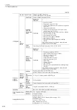
Safe Performance

Items

Standards

Performance Level

Safety Integrity Level

IEC 61508 

SIL2

IEC 62061 

SILCL2

Probability of Dangerous Failure per Hour

IEC 61508,
IEC 62061 

PFH 

 1.7

×

10

-9 

[1/h]

 (0.17% of SIL2)

Category

EN 954-1 

Category 3

Performance Level

EN ISO 13849-1 

PL d (Category 3)

Mean Time to Dangerous Failure of Each 

Channel

EN ISO 13849-1

MTTFd: High 

Average Diagnostic Coverage

EN ISO 13849-1

DCave: Low

Stop Category

IEC 60204-1 

Stop category 0

Safety Function

IEC 61800-5-2 

STO

Proof test Interval

IEC 61508

10 years

Summary of Contents for JUSP-MD D01A Series

Page 1: ...onal Motor Analog Voltage and Pulse Train References V Series AC Servo Drives USER S MANUAL For Use with Large Capacity Models Design and Maintenance MANUAL NO SIEP S800001 68B 1 2 3 4 5 6 7 8 9 10 Ou...

Page 2: ...liability is assumed with respect to the use of the information contained herein Moreover because Yaskawa is con stantly striving to improve its high quality products the information contained in this...

Page 3: ...ding drive unit SERVO PACK and converter Servo System A servo control system that includes the combination of a servo drive with a host controller and peripheral devices Analog pulse model A multi win...

Page 4: ...rameter will be effective Indicates the parameter classification Indicates the minimum setting unit for the parameter Torque Position Speed Indicates the setting range for the parameter The notation n...

Page 5: ...Multi Winding Drive System Rotational Motors No SIEP S800001 85 V Series User s Manual For Use with Large Capacity Models Design and Maintenance Multi Winding Drive System Rotational Motor Analog Vol...

Page 6: ...sibly result in loss of life or serious injury Indicates precautions that if not heeded could result in relatively serious or minor injury damage to the product or faulty operation In some situations...

Page 7: ...ure to make the system modifications The multi turn limit value need not be changed except for special applications Changing it inappropriately or unintentionally can be dangerous If the Multiturn Lim...

Page 8: ...contactor is turned OFF Installation disassembly or repair must be performed only by authorized personnel Failure to observe this warning may result in electric shock or injury The person who designs...

Page 9: ...han fumigation must be used Example Heat treatment where materials are kiln dried to a core temperature of 56 C for 30 minutes or more If the electronic products which include stand alone products and...

Page 10: ...r opening in the main circuit terminals Make sure that no part of the core wire comes into contact with i e short circuits adjacent wires Install a battery at either the host controller or the multi w...

Page 11: ...stop in the zero clamp state when overtravel occurs Failure to observe this caution may cause workpieces to fall due to overtravel Before you start operation always set the moment of inertia ratio Pn1...

Page 12: ...are sometimes shown without covers or protective guards Always replace the cover or protective guard as specified first and then operate the products in accordance with the manual The drawings present...

Page 13: ...d product in a manner in which it was not originally intended 5 Causes that were not foreseeable with the scientific and technological understanding at the time of ship ment from Yaskawa 6 Events for...

Page 14: ...property Systems that require a high degree of reliability such as systems that supply gas water or electricity or systems that operate continuously 24 hours a day Other systems that require a similar...

Page 15: ...PACKs SGDV J converters SGDV COA Machinery Directive 2006 42 EC EN ISO13849 1 2008 EN 954 1 EMC Directive 2004 108 EC EN 55011 group 1 class A EN 61000 6 2 EN 61800 3 Low Voltage Directive 2006 95 EC...

Page 16: ...8 IEC 62061 PFH 1 7 10 9 1 h 0 17 of SIL2 Category EN 954 1 Category 3 Performance Level EN ISO 13849 1 PL d Category 3 Mean Time to Dangerous Failure of Each Channel EN ISO 13849 1 MTTFd High Average...

Page 17: ...nit Model Designation 1 14 1 6 2 SERVOPACK Model Designation 1 15 1 6 3 Converter Model Designation 1 15 1 7 Combinations for Multi Winding Drive Systems 1 16 1 8 Inspection and Maintenance of a Multi...

Page 18: ...Brake Unit 3 41 3 9 3 Setting the Dynamic Brake Unit 3 42 3 9 4 Setting the Dynamic Brake Answer Function 3 43 3 9 5 Installation Standards 3 44 3 9 6 Connections 3 44 3 10 Noise Control and Measures...

Page 19: ...or 6 5 52 5 7 2 Switching Other Than Internal Set Speed Control Pn000 1 7 8 or 9 5 54 5 7 3 Switching Other Than Internal Set Speed Control Pn000 1 A or B 5 54 5 8 Limiting Torque 5 55 5 8 1 Internal...

Page 20: ...6 37 6 6 1 Switching Gain Settings 6 37 6 6 2 Manual Adjustment of Friction Compensation 6 41 6 6 3 Current Control Mode Selection Function 6 43 6 6 4 Current Gain Level Setting 6 43 6 6 5 Speed Detec...

Page 21: ...oting of Alarms 9 6 9 2 Warning Displays 9 21 9 2 1 List of Warnings 9 21 9 2 2 Troubleshooting of Warnings 9 22 9 3 Troubleshooting Malfunction Based on Operation and Conditions of the Servomotor 9 2...

Page 22: ...4 1 Ratings 1 8 1 4 2 Basic Specifications 1 9 1 4 3 Speed Position Torque Control 1 12 1 5 Internal Block Diagrams 1 13 1 5 1 Internal Block Diagram of the Multi Winding Drive Unit 1 13 1 5 2 Intern...

Page 23: ...nected to the encoder of a servomotor and it performs position speed or torque control It controls the SERVOPACKs through local communications cables SERVOPACKs and Converters The SERVOPACKs and conve...

Page 24: ...al com puter Use the special personal computer cable to make the connection Digital operator connector CN54 Used to connect to a digital operator or personal computer RS422 Connectors CN9A and CN9B Do...

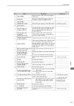
Page 25: ...switch S1002 Do not use this switch MS1 LED indicator This indicator cannot be used MMA MM2 MM3 and MM4 LED indicators Lights green when local communications are ready Panel operator keys Used to set...

Page 26: ...t these terminals to P and N on the con verter Dynamic brake unit connection terminals DU DV and DW Use these terminals to connect the dynamic brake unit Do not connect servomotors to these terminals...

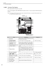
Page 27: ...104 are equivalent outputs It is normally not necessary to connect CN104 SERVOPACK converter I O connector CN901 Connect this connector to CN901 on the SERVO PACK Charge indicator Lights orange when t...

Page 28: ...inals P and N is abnormal Converter LED indicator FANSTOP Lights red when an error occurs while the con verter fan is running Converter LED indicator MC FAULT Lights red when an error occurs when the...

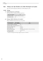
Page 29: ...ERVOPACKs and converters are as shown below Refer to 3 8 Selecting and Connecting a Regenerative Resistor Unit for details Model JUSP MD D 3D Control Power Supply 24 VDC 15 to 15 0 6 A Overvoltage Cat...

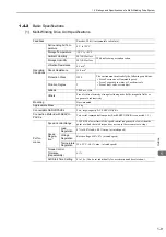
Page 30: ...on Degree 2 Altitude 1 000 m or less Others Free of static electricity strong electromagnetic fields magnetic fields or exposure to radioactivity Mounting Base mounted Approximate Mass 2 6 kg Connecta...

Page 31: ...unctions Positioning completion COIN Speed coincidence detection V CMP Rotation detection TGON Servo ready S RDY Torque limit detection CLT Speed limit detection VLT Brake BK Warning WARN Near NEAR Re...

Page 32: ...age Humidity 90 RH or less Vibration Resistance 4 9 m s2 Shock Resistance 19 6 m s2 Protection Class IP10 The environment must satisfy the following conditions Free of corrosive or flammable gases Fre...

Page 33: ...forward reverse external torque limit signal speed 1 to 3 selection Servomotor stops or another control method is used when both are OFF Position Control Performance Feedforward Compensation 0 to 100...

Page 34: ...ower supply L1 B2 L2 24 V 0 V U V W 5 V Voltage sensor gate drive 1 Voltage sensor Fan 2 L3 MC drive Voltage sensor 2 CHARGE P24 V Fan 1 SPD 15 V 24 V 2 P N 24 V 24C 24 V 24C CN103 CN104 CN901 Fan Tem...

Page 35: ...st 2nd digits MD Multi winding drive unit 5th 6th digits Interface Specifications Code Interface 01 Analog voltage and pulse train reference rotational servomotor 1st 2nd digits 5th 6th digits 7th dig...

Page 36: ...ication 00 Standard 7th digit Design Revision Order 1st 2nd 3rd digits 4th digit 5th 6th digits 7th digit 101 J F1 A 8th 9th 10th digits 000 8th 9th 10th digits Hardware Specifications Code Specificat...

Page 37: ...under the following operating conditions Surrounding air temperature Annual average of 30 C Load factor 80 max Operation rate 20 hours day max Main Circuit Power Supply Voltage Servomotor SERVOPACKs...

Page 38: ...1 1 Names and Functions 2 2 2 1 2 Display Selection 2 2 2 1 3 Status Display 2 3 2 2 Utility Functions Fn 2 4 2 3 Parameters Pn 2 5 2 3 1 Parameter Classification 2 5 2 3 2 Notation for Parameters 2 5...

Page 39: ...UP Key and the DOWN Key simultaneously Be sure to remove the cause and then reset the alarm Key No Key Name Function MODE SET Key To select a display To set the set value UP Key To increase the set v...

Page 40: ...ing 10 min 1 Always lights in torque control Note If there is noise in the reference voltage during speed control the horizontal line at the far left edge of the panel operator display may flash Refer...

Page 41: ...lay shown on the left appears 5 Pressing the UP Key will rotate the servomotor in the for ward direction Pressing the DOWN Key will rotate the servomotor in the reverse direction The rotation directio...

Page 42: ...g Parameters Parameters for tuning con trol gain and other parame ters Set Pn00B 0 to 1 There is no need to set each parameter individually Pn406 Emergency Stop Torque Setting Range 0 to 800 1 800 Aft...

Page 43: ...ue for the 1st digit of parameter Pn002 is x Indicates that the value for the 2nd digit of parameter Pn002 is x Pn002 2 x or n x Pn002 3 x or n x Indicates that the value for the 3rd digit of paramete...

Page 44: ...Key In this case 6789 is set 3 Press the DATA SHIFT Key The middle four digits will be displayed In this case 0000 is displayed Press the DATA SHIFT Key to move to other digits and change the value by...

Page 45: ...winding drive unit After the saving is completed press the DATA SHIFT Key for approximately one second Pn522 is displayed again cont d Step Display after Operation Keys Operation MODE SET DATA Step Di...

Page 46: ...e for Motor Rotating Speed The following table outlines the procedures necessary to view the motor rotating speed Un000 Step Display after Operation Keys Operation 1 Press the MODE SET Key to select t...

Page 47: ...19 3 3 5 Example of I O Signal Connections in Torque Control 3 20 3 4 I O Signal Allocations 3 21 3 4 1 Input Signal Allocations 3 21 3 4 2 Output Signal Allocations 3 25 3 5 Examples of Connection to...

Page 48: ...on 3 43 3 9 5 Installation Standards 3 44 3 9 6 Connections 3 44 3 10 Noise Control and Measures for Harmonic Suppression 3 48 3 10 1 Wiring for Noise Control 3 48 3 10 2 Precautions on Connecting Noi...

Page 49: ...he front cover attached when using the SERVOPACK 1 Multi Winding Drive Unit The pin arrangements of the control power supply connectors CN7A CN7B are given below CN7A B Connectors Terminal Name Specif...

Page 50: ...tor terminals CN103 CN104 Control power input connectors CN103 is the 24 VDC 15 input CN104 takes the same input but it is normally not necessary to connect it DU DV DW Dynamic brake unit terminals Co...

Page 51: ...utput terminals Connect these terminals to the P and N terminals on the SERVO PACK Ground terminal Connect this terminal to the power supply ground terminal and then ground it B1 B2 Regenerative resis...

Page 52: ...l ducts take into account the reduction of the allowable current Use a heat resistant wire under high surrounding air or panel temperatures where polyvinyl chloride insulated wires will rapidly deteri...

Page 53: ...Size in mm2 AWG Connector Model Made by Tyco Electronics Japan G K Connector Model Made by Tyco Electronics Japan G K Connector Model Made by Tyco Electronics Japan G K Control power supply connector...

Page 54: ...of SERVOPACK and Converter Terminal Symbols Screw Size for Terminals Tightening Torque N m Wire Size AWG SGDV 101J SGDV COA5EDA SERVOPACK P N M8 15 0 Bus bar attached to the converter U V W M8 3 0 1...

Page 55: ...ON the main circuit power supply after the control power supply When you turn OFF the power first turn OFF the power for the main circuit and then turn OFF the control power Configure the system so t...

Page 56: ...CN41A B CN9A B CN54 CN4 CN21 SERVOPACK 1 CN6 SERVOPACK 2 CN6 CN1 32 31 24 V 1Ry 1D ALM ALM 0 V Power supply Single phase 100 200 VAC 3QF 3FLT 4SA 1KM 2KM 1FLT 2FLT R S T Power supply Three phase 400...

Page 57: ...machine The signal cable conductors are as thin as 0 2 mm2 or 0 3 mm2 Do not impose excessive bending force or tension Use a molded case circuit breaker 1QF or fuse to protect the main circuit The SER...

Page 58: ...odels that are compliant with UL standards The table above also provides the nominal values of current capacity and inrush current Select a fuse and a molded case circuit breaker which meet the cutoff...

Page 59: ...ations Discharging Time min SERVOPACK Model SGDV Converter Model SGDV COA Three phase 400 VAC 101J 5EDA 10 WARNING High voltage may still remain in the SERVOPACKs and converters even after you turn OF...

Page 60: ...and the converter The bus bars can be connected in any direction CN901 I O signal connector between the SERVOPACK and converter CN103 Control power supply input connector I O signal connection cable...

Page 61: ...selected Stops reference pulse input when ON 5 4 8 P OT N OT 42 43 Forward run prohibited Reverse run prohibited With overtravel prevention Stops servomotor when movable part travels beyond the allowa...

Page 62: ...pt the servo ON S ON signal 5 10 4 PAO PAO 33 34 Phase A signal Encoder output pulse signals for two phase pulse train with 90 phase differential 5 3 6 5 9 5 PBO PBO 35 36 Phase B signal PCO PCO 19 20...

Page 63: ...ons of safety function signals CN8 on the SERVOPACKs Note The safety function signals can be connected only to a SERVOPACK Do not use pins 1 and 2 because they are connected to the internal circuits S...

Page 64: ...LO1 ALO2 ALO3 37 38 39 CN1 D A D A 5 5 5 2 Backup battery 2 8 to 4 5 V Servo ON Servo ON when ON Reverse run prohibited Prohibited when OFF Forward run prohibited Prohibited when OFF Alarm reset Reset...

Page 65: ...12 11 150 8 7 150 4 4 4 PULS SIGN CLR Multi winding drive unit Alarm code output OFF for alarm Max operating voltage 30 VDC Max output current 20 mA DC Servo ON Servo ON when ON Reverse run prohibite...

Page 66: ...N1 D A D A Multi winding drive unit 1 4 2 3 2 Backup battery 2 8 to 4 5 V Servo ON Servo ON when ON Reverse run prohibited Prohibited when OFF Forward run prohibited Prohibited when OFF Alarm reset Re...

Page 67: ...can be checked using the parameters Pn50A Pn50B Pn50C Pn50D and Pn515 Pn000 1 Setting Control Method Selection CN1 Pin No 40 41 42 43 44 45 46 0 Speed control S ON Uses as P CON P OT N OT ALM RST P CL...

Page 68: ...s resulting in an unexpected machine operation Input Signal Names and Parameters Validity Level Input Signal CN1 Pin Numbers Connection Not Required Processed inside the Multi Winding Drive Unit 40 41...

Page 69: ...4 5 6 7 8 H SPD A 9 A B C D E F Internal Set Speed Control Pn50C 2 L SPD B 0 1 2 3 4 5 6 7 8 H SPD B 9 A B C D E F Control Method Selection Pn50C 3 L C SEL 0 1 2 3 4 5 6 7 8 H C SEL 9 A B C D E F Zero...

Page 70: ...5 Changes the allocation of S ON from CN1 40 to CN1 45 5 Display flashes Press the MODE SET Key The data flashes and is saved 6 Press the DATA SHIFT Key for approximately one second to return to the d...

Page 71: ...0F Pn510 Pn512 and Pn514 1 Checking Factory Settings Factory settings can be checked using the following parameters Signal Level Voltage Level Contact ON Low L level 0 V Close OFF High H level 24 V Op...

Page 72: ...circuit Output Signal Names and Parameters Output Signal CN1 Pin Numbers Invalid not use 25 26 27 28 29 30 Positioning Completion Pn50E 0 COIN 1 2 3 0 Speed Coincidence Detection Pn50E 1 V CMP 1 2 3...

Page 73: ...FT Key to select the third digit from the right Press the DOWN Key to set 0 Sets TGON Invalid 4 Display flashes Press the MODE SET Key The data flashes and is saved 5 Press the DATA SHIFT Key for appr...

Page 74: ...pulse and position error clear signal from the host controller can be either a line driver output or open collector output The position reference input circuits are shown below by output type Analog V...

Page 75: ...hip between the pull up voltage Vcc and the pull up resistance R1 Before wiring confirm that the specifications of the host controller satisfy the values shown in the following table Pull up voltage V...

Page 76: ...nit uses bidirectional photocoupler Select either the sink circuit or the source circuit according to the specifications required for each machine Note The connection examples in 3 3 3 to 3 3 5 show s...

Page 77: ...is necessary to make an input signal redundant Input Signal Connection Example 24 V power supply Fuse Switch 0 V Motor HWBB1 HWBB1 HWBB2 HWBB2 SERVOPACK 1 Converter 1 Control circuit Control circuit...

Page 78: ...open collector output circuit through a photocoupler relay or line receiver circuit Note The maximum allowable voltage and maximum current capacity for open collector output circuits are as follows V...

Page 79: ...t CN1 connector pins 33 and 34 phase A signal 35 and 36 phase B signal and 19 and 20 phase C signal on the multi winding drive unit are explained below The following signals are output on the line dri...

Page 80: ...signal are as follows SERVOPACK 1 CN8 CN8 8 24 V power supply EDM1 7 0 V Host controller EDM1 SERVOPACK 2 8 EDM1 7 EDM1 Type Signal Name Pin No Output Status Meaning Output EDM1 CN8 8 CN8 7 ON Both th...

Page 81: ...he multi winding drive unit and SERVOPACK are 1 1 so two communications ports are provided on the multi winding drive unit Note 1 Attach a terminator to the CN6B connector on the SERVOPACK 2 The CN41A...

Page 82: ...at is used 2 To prevent the influence of external noise we recommend you connect a ferrite core on the motor end of the encoder cable using two turns 3 represents shielded twisted pair wires Signal Na...

Page 83: ...der cable with a battery case that is specified by Yaskawa Refer to the multi winding drive system catalog for details When Installing a Battery on the Host Controller Insert a diode near the battery...

Page 84: ...Specified Regenerative Resistor Unit If you use non specified regenerative resistor units contact your Yaskawa representative or the sales depart ment for more details Set Pn600 to the allowable capa...

Page 85: ...resistor in Pn600 Regenerative Resistor Capacity Be sure to set the regenerative resistor capacity Pn600 to a value that is in accordance with the allowable capacity of the actual regenerative resisto...

Page 86: ...fan and natural convection cooling If you use a non specified regenerative resistor unit follow the specifications of the regenerative resistor unit when you install it When the regenerative resistor...

Page 87: ...dynamic brake contactor to CN115 on the SERVOPACK A dynamic brake unit is required for each SERVOPACK Set the dynamic brake in parameter Pn001 of the multi winding drive unit Do not mis takenly chang...

Page 88: ...et Pn601 to 20 of the resistor capacity of your dynamic brake 3 Not Using a Dynamic Brake Set Pn001 to n 2 Not necessary to set Pn00D Set Pn601 to 0 Parameter Meaning When Enabled Classification Pn001...

Page 89: ...1 41 is ON closed while the DB is applied n 2 Detects DB contactor errors when the input signal of CN1 42 is ON closed while the DB is applied n 3 Detects DB contactor errors when the input signal of...

Page 90: ...istor from a company other than Yaskawa follow the specifications of the dynamic brake resistor when you install it 3 9 6 Connections 1 Using a Yaskawa Dynamic Brake Unit A dynamic brake contactor is...

Page 91: ...contacts is input to CN1 45 To indicate an error if the input signal to CN1 45 turns OFF open while the dynamic brake is activated the Pn515 parameter in the multi winding drive unit must be set to n...

Page 92: ...error if the input signal to CN1 45 turns OFF open while the dynamic brake is activated the Pn515 parameter in the multi winding drive unit must be set to n E If the dynamic brake answer signal is not...

Page 93: ...ws connecting dynamic brake resistors for the SERVOPACK for one winding When connecting dynamic brake resistors for actual operation refer to the following figure and connect resis tors for two windin...

Page 94: ...parated from the I O signal cables and the encoder cables with a gap of at least 30 cm Do not share the power supply with an electric welder or electrical discharge machine If the SERVOPACK is placed...

Page 95: ...be sure to ground the ground terminal If the servomotor is grounded via the machine a switching noise current will flow from the main circuit of the SERVOPACK and converter through the stray capacita...

Page 96: ...em together Some noise filters have large leakage currents The grounding measures taken also affects the extent of the leakage current If necessary select an appropriate leakage cur rent detector or l...

Page 97: ...inside a control panel first connect the noise filter ground wire and the ground wires from other devices inside the control panel to the ground plate for the control panel then ground the plates Shi...

Page 98: ...red Connect a reactor as shown in the following figure Note 1 Connection terminals for DC reactor 1 and 2 are short circuited at shipment Remove the lead wire for short circuit and connect a DC reacto...

Page 99: ...rence 4 3 4 3 1 Inspecting Connection and Status of Input Signals 4 4 4 3 2 Trial Operation in Speed Control 4 6 4 3 3 Trial Operation under Position Control from the Host Controller with the Multi Wi...

Page 100: ...that has been stored for a long period of time perform the inspec tion according to the procedures described in 1 8 Inspection and Maintenance of a Multi Winding Drive System 2 Multi Winding Drive Sys...

Page 101: ...Refer to 4 4 4 Trial Operation in Position Control Position Control with Host Controller Refer to 4 4 3 Trial Operation under Position Control from the Host with the SERVOPACK used for Speed Control...

Page 102: ...and reverse run prohibited N OT input signals must be ON L level i e the servomotor must be able to run in forward and reverse Settings CN1 42 and CN1 43 must be ON low or Pn50A 3 and Pn50B 0 must be...

Page 103: ...ion of SigmaWin 8 4 Monitoring Input Signals 3 4 1 Input Signal Allocations 4 Input the S ON signal then make sure that the display of the panel operator is as shown below If an alarm display appears...

Page 104: ...wer supply to the multi winding drive system 3 3 3 Example of I O Sig nal Connections in Speed Control 2 Adjust the speed reference input gain Pn300 5 3 1 Basic Settings for Speed Control 3 Turn ON th...

Page 105: ...Visually check that the servomotor rotates once per second with a speed reference of 60 min 1 Note If the speed of the servomotor is not correct check the reference sent by the host controller 8 1 Lis...

Page 106: ...rence for a comparatively large number of motor rotations from the host controller so that the servomotor will rotate at a constant speed 12 Check the reference pulse speed input to the SERVOPACK from...

Page 107: ...ACK is used without the jumper connector inserted into CN8 no current will flow to the servomotor and no torque will be output In this case Hbb will be dis played on the panel operator or the digital...

Page 108: ...erence unit 4 3 Trial Operation for Servomotor without Load from Host Reference 6 Check the settings of parameters for control method used set in step 2 again Check that the servomotor rotates matchin...

Page 109: ...23 5 3 4 Speed Reference Filter 5 23 5 3 5 Zero Clamp Function 5 24 5 3 6 Encoder Output Pulses 5 26 5 3 7 Setting Encoder Output Pulse 5 27 5 3 8 Setting Speed Coincidence Signal 5 28 5 4 Position Co...

Page 110: ...ing Output Torque Limiting during Operation 5 60 5 9 Absolute Encoders 5 61 5 9 1 Connecting the Absolute Encoder 5 62 5 9 2 Absolute Data Request Signal SEN 5 64 5 9 3 Battery Replacement 5 65 5 9 4...

Page 111: ...g voltage torque reference Use to output the required amount of torque for operations such as stopping on contact 5 5 Torque Control n 3 Internal Set Speed Con trol Uses three operating speeds set in...

Page 112: ...e the servo ON signal or turn ON OFF the AC power supply to start or stop Doing so will degrade inter nal elements and lead to accident Input the servo ON signal while the servomotor stops While the s...

Page 113: ...igmaWin trace waveforms are shown in the above table Parameter Forward Reverse Reference Direction of Motor Rotation and Encoder Output Pulse Applicable Overtravel OT Pn000 n 0 Sets CCW as for ward di...

Page 114: ...when the brake is released Set the parameter Pn001 n 1 to bring the servomotor to zero clamp state after stopping to prevent a workpiece from falling Other axes to which external force is applied Ove...

Page 115: ...The servomotor stopping method when an overtravel P OT N OT signal is input while the servomotor is operating can be set with parameter Pn001 Always connect a dynamic brake circuit for these settings...

Page 116: ...OFF to ON even if overtravel status exists The warning output will be held for one second after the overtravel status no longer exists and it will then be cleared automatically Related Parameter Pn406...

Page 117: ...with brakes is a de energization brake which is used only to hold and cannot be used for braking Use the holding brake only to hold a stopped servomotor Servomotor Vertical Shaft Holding brake Shaft w...

Page 118: ...ake signal BK and the brake power supply to form a brake ON OFF circuit The following dia gram shows a standard wiring example The timing can be easily set using the brake signal BK Main Circuit Power...

Page 119: ...k the total time the brake is applied for the system Depending on the surge absorber the total time the brake is applied can be changed Configure the relay circuit to apply the holding brake by the em...

Page 120: ...ed to the same output terminal the signals are output with OR logic For the BK signal do not use the output terminal that is already being used for another signal Pn506 Brake Reference Servo OFF Delay...

Page 121: ...ng Unit Factory Setting When Enabled 10 to 100 10 ms 50 Immediately Setup Speed Position Torque Speed Position Torque BK Signal Output Conditions When Servomotor Rotating The BK signal goes to high le...

Page 122: ...pping methods in 9 1 1 List of Alarms Dynamic braking DB is used for emergency stops The DB circuit will operate fre quently if the power is turned ON and OFF or the S ON signal is ON and OFF with a r...

Page 123: ...speed stopping The speed reference is set to 0 to stop quickly Note The setting of Pn00B 1 is effective for position control and speed control Pn00B 1 will be ignored for torque control and only the...

Page 124: ...tting Unit Factory Setting When Enabled 20 to 50000 1 ms 20 Immediately Setup If the control power supply makes control impossible during an instantaneous power interruption the same operation will be...

Page 125: ...the overload warning level Pn52B This protective function enables the warning out put signal WARN to serve as a protective function and to be output at the best timing for your system The following g...

Page 126: ...motor Pn52C Derating of motor base current The following graph shows an example of the detection of an overload alarm when Pn52C is set to 50 The calculation for the overload of motors starts at 50 o...

Page 127: ...e operator as 006 00 Connect the pins for the V REF signal and SG to the speed reference output terminal on the host controller when using a host controller such as a programmable controller for posit...

Page 128: ...atic adjustment uses the automatic adjustment parameter for reference offset Fn009 Manual adjustment uses the manual adjustment parameter for refer ence offset Fn00A Pn300 Speed Reference Input Gain C...

Page 129: ...operator using the following steps Note The automatic adjustment of reference offset Fn009 cannot be used when a position loop has been formed with a host controller Use the manual adjustment of refe...

Page 130: ...eference offset manually with the panel operator using the following steps Step Display after Operation Keys Operation 1 Press the MODE SET Key to select the utility function 2 Press the UP or the DOW...

Page 131: ...rder lag filter to the analog speed reference V REF input Note The user need not usually change the setting A setting value that is too large however will slow down response Check the response charact...

Page 132: ...e gain switching function is used adjusting the 2nd position loop gain Pn106 is required as well For details refer to 6 6 1 Switching Gain Settings 1 Factory set Input Signal Allocations Pn50A 0 0 Whe...

Page 133: ...servomotor is set the actual speed will be limited to the max imum speed of the servomotor Type Connector Pin Number Setting Meaning Input ZCLAMP Must be allocated ON closed The zero clamp function w...

Page 134: ...utput pulse phase A These encoder pulse output pins out put the number of pulses per motor revolution that is set in Pn212 Phase A and phase B are different from each other in phase by an electric ang...

Page 135: ...per limit of the pulse frequency is approximately 1 6 Mpps The servomotor speed is limited if the setting value of the encoder output pulses Pn212 is large An overspeed of encoder output pulse rate al...

Page 136: ...for details The V CMP signal is output when the difference between the reference speed and actual motor speed is below this setting Example The V CMP signal is output at 1900 to 2100 min 1 if the Pn50...

Page 137: ...r counter Position control section Position feedback Speed feedback Current feedback Torque reference Speed reference Clear signal input Position reference ENC M Power amplifier Divider Speed conversi...

Page 138: ...2 n 4 4 n 5 Sign pulse train Negative logic n 6 CW CCW pulse train Negative logic H level PULS CN1 7 SIGN CN1 1 1 L level PULS CN1 7 SIGN CN1 1 1 L level CW CN1 7 CCW CN1 1 1 L level CW CN1 7 CCW CN1...

Page 139: ...ler 150 4 7 k Photocoupler 150 4 7 k Photocoupler FG FG Use a shielded cable for I O signals and ground both ends of the shield Connect the shield of the cable on the multi winding drive unit side to...

Page 140: ...represents twisted pair wires Use a shielded cable for I O signals and ground both ends of the shield Connect the shield of the cable on the multi winding drive unit side to the connector shell so tha...

Page 141: ...reference fre quency in case of open collector output 200 kpps t1 t2 t3 t7 0 025 s t4 t5 t6 0 5 s 0 125 s T 0 125 s Sign SIGN H Forward reference L Reverse reference CW CCW pulse train Maximum referen...

Page 142: ...ear Operation This parameter determines when the position error should be set to zero according to the condition of the multi winding drive unit Any of three clearing modes can be selected with Pn200...

Page 143: ...nal for use For details refer to 3 4 1 Input Signal Allocations to Input Terminals CAUTION Unexpected operation may occur if a position reference pulse is input before the multiplier changes Always us...

Page 144: ...f the reference pulse Type Signal Name Connector Pin Number Setting Meaning Output PSELA Must be allocated ON closed The multiplier of the input reference pulse is enabled OFF open The multiplier of t...

Page 145: ...tory Setting When Enabled 1 to 1073741824 1 4 After restart Setup Pn210 Electronic Gear Ratio Denominator Classification Setting Range Setting Unit Factory Setting When Enabled 1 to 1073741824 1 1 Aft...

Page 146: ...bit 1048576 20 bit 3 Determine the reference unit used Reference unit 0 001 mm 1 m Reference unit 0 01 Reference unit 0 005 mm 5 m 4 Calculate the travel dis tance per load shaft revo lution Referenc...

Page 147: ...17 is shown below Pn216 Position Reference Acceleration Deceleration Time Constant Classification Setting Range Setting Unit Factory Setting When Enabled 0 to 65535 0 1 ms 0 Immediately after the serv...

Page 148: ...output unexpectedly reduce the set value until it is no longer output If the position error is kept to a minimum when the positioning completed width is small use Pn207 3 to change output timing for t...

Page 149: ...difference between the number of reference pulses output by the host controller and the travel distance of the servomotor position error is less than the set value Note Normally the value of Pn524 sh...

Page 150: ...the INHIBIT signal for use For details refer to 3 4 1 Input Signal Allocations to Input Terminals To use the reference pulse inhibit function set Pn000 1 to 1 5 7 or 8 Note Reference pulse inhibit fu...

Page 151: ...3 0 V Factory setting Note The value is 30 but it will be displayed on the operator as 0003 0 Connect the pins for the T REF signal and SG to the analog reference output terminal on the host controlle...

Page 152: ...very low speed the offset needs to be eliminated with the offset adjustment func tion Use either automatic adjustment or manual adjustment Automatic adjustment uses the automatic adjustment parameter...

Page 153: ...el operator using the following steps Note The automatic adjustment of reference offset Fn009 cannot be used when a position loop has been formed with the host controller Use the manual adjustment of...

Page 154: ...with the panel operator using the following steps Step Display after Operation Keys Operation 1 Press the MODE SET Key to select the utility function 2 Press the UP or the DOWN Key to select Fn00b 3 P...

Page 155: ...imit The following signal is output when the motor speed reaches the limit speed Note Use parameter Pn50F 1 to allocate the VLT signal for use For details refer to 3 4 2 Output Signal Allocations 2 Sp...

Page 156: ...the V REF and the value of Pn407 is enabled when Pn002 1 is set to 1 The setting in Pn300 determines the voltage level to be input as the limit value Polarity has no effect When Pn300 is set to 6 00 f...

Page 157: ...es the basic settings for the internal set speeds 1 Signal Setting The following input signals are used to switch the operating speed Factory set Input Signal Allocations P CON P CL and N CL Changing...

Page 158: ...0000 1 min 1 100 Immediately Setup Pn302 Internal Set Speed 2 Classification Setting Range Setting Unit Factory Setting When Enabled 0 to 10000 1 min 1 200 Immediately Setup Pn303 Internal Set Speed 3...

Page 159: ...t start function The shock that results when the speed is changed can be reduced by using the soft start function SPEED1 Servomotor speed SPEED3 SPEED2 SPEED1 SPEED2 SPEED3 0 OFF ON Stop P CL SPD A N...

Page 160: ...d Control Speed Control After restart Setup n 5 Internal Set Speed Control Position Control n 6 Internal Set Speed Control Torque Control n 7 Position Control Speed Control n 8 Position Control Torque...

Page 161: ...locate the SPD D SPD A and SPD B signals for use For details refer to 3 4 1 Input Signal Allocations SPEED1 SPEED3 SPEED2 SPEED1 SPEED2 SPEED3 0 P CL COIN N CL t1 Motor speed ON Decelerating to a stop...

Page 162: ...llocations for Each Signal Pn50A 0 1 Type Signal Name Connector Pin Number Setting Pn000 1 Setting and Control Method n 7 n 8 n 9 Input P CON CN1 41 ON closed Speed Torque Speed OFF open Position Posi...

Page 163: ...al torque limit Always limits torque by setting the parameter 5 8 1 External torque limit Limits torque by input signal from the host controller 5 8 2 Torque limiting by analog voltage reference Assig...

Page 164: ...on of the servomotor Type Signal Name Connector Pin Number Setting Meaning Limit value Input P CL CN1 45 Factory setting ON closed Forward external torque limit ON The smaller value of these set tings...

Page 165: ...g voltage reference is performed in the speed control There is no polarity in the input voltage of the analog voltage reference for torque limiting The absolute val ues of both and voltages are input...

Page 166: ...Torque Reference Input Gain Classification Setting Range Setting Unit Factory Setting When Enabled 10 to 100 0 1 V 30 Rated torque at 3 0 V Immediately Setup Pn402 Forward Torque Limit Classification...

Page 167: ...it input After restart Setup Pn300 T REF V REF N CL P CL Pn101 Pn100 Pn400 T REF filter time constant Pn415 Torque limit value Speed reference Pn404 P CL ON Pn402 Pn405 Reverse external torque limit N...

Page 168: ...nit Factory Setting When Enabled Setup 0 to 800 1 800 Immediately Pn403 Reverse Torque Limit Classification Setting Range Setting Unit Factory Setting When Enabled Setup 0 to 800 1 800 Immediately Pn4...

Page 169: ...bsolute encoder as an incremental encoder The rotational serial data output range for a large capacity V series absolute position detecting system is different from the range for previous series syste...

Page 170: ...s shielded twisted pair wires 4 When using an absolute encoder provide power by installing an encoder cable with a JUSP BA01 E Battery Case or install a battery on the host controller PCO 4 2 SG SEN 3...

Page 171: ...able with a battery case that is specified by Yaskawa Refer to the multi winding drive system catalog for details When Installing a Battery on the Host Controller Insert a diode near the battery to pr...

Page 172: ...er sends a request to the multi winding drive unit for the absolute data 4 7 k SEN 4 CN1 SG 2 5 V 0 V 100 0 V 0 1 F Host controller Multi winding drive unit High level Approx 1 mA 7406 or the equivale...

Page 173: ...will be displayed even if the battery voltage drops below the specified value after these 4 seconds If Pn008 0 is set to 1 alarm detection will be always enabled after the ALM signal outputs max 5 sec...

Page 174: ...ery turn OFF the control power supply to clear the absolute encoder battery error alarm A 830 6 Turn ON the control power supply 7 Check that the alarm display has been cleared and that the multi wind...

Page 175: ...bsolute encoder with Fn008 1 Precautions on Setup and Reinitialization The write prohibited setting parameter Fn010 must be set to Write permitted P 0000 Set up or reinitialize the encoder when the se...

Page 176: ...eft appears 4 Continue pressing the UP Key until PGCL5 is displayed Note If the wrong key is pressed no oP will flash for about one second and it will return to the utility func tion Start the operati...

Page 177: ...ute Data Reception Sequence 1 Set the SEN signal at ON high level 2 After 100 ms the system is set to rotational serial data reception standby and the incremental pulse up down counter is cleared to z...

Page 178: ...formula PE M R PO PS MS R PS PM PE PS Note The following formula applies in reverse mode Pn000 0 1 PE M R PO PS MS R PS PM PE PS Setting of the Encoder Output Pulses Pn212 Formula of the Initial Incr...

Page 179: ...nal cannot be OFF while the servomotor power is ON Output example of alarm contents are as shown below Data Transfer Method Start stop Synchronization ASYNC Baud rate 9600 bps Start bits 1 bit Stop bi...

Page 180: ...05 m 1 The case in which the relationship between the turntable revolutions and motor revolutions is m 100 and n 3 is shown in the following graph Pn205 is set to 99 Pn205 100 1 99 Note This parameter...

Page 181: ...Name Alarm Code Output Meaning A CC0 Multiturn Limit Dis agreement ALO1 ALO2 ALO3 Different multiturn limits have been set in the encoder and the multi winding drive unit ON L OFF H ON L Step Display...

Page 182: ...at the host controller For details refer to 9 1 1 List of Alarms 3 Alarm Reset Method If a servo alarm ALM occurs use one of the following methods to reset the alarm after eliminating the cause of the...

Page 183: ...N signal for use For details refer to 3 4 2 Output Signal Allocations 2 Related Parameters Set the output method for alarm codes in Pn001 3 For details on alarm codes refer to 2 Alarm Code Output Sign...

Page 184: ...ed when the SEN signal is ON high level before S RDY is output For details on the hard wire base block function refer to 5 11 1 Hard Wire Base Block HWBB Function 1 Signal Specifications Note 1 Use pa...

Page 185: ...r module that controls the motor current and the motor current is shut off Refer to the diagram below Note For safety function signal connections the input signal is the 0 V common and the output sign...

Page 186: ...hat situation The maximum motor rotation angle is 1 6 of a rotation This is the converted rotation angle for the motor shaft The HWBB function does not shut off the power to the SERVOPACK and converte...

Page 187: ...signals HWBB sig nals are shown below Connection Example HWBB1 HWBB2 S ON SERVOPACK state ON ON HWBB state BB state Operating OFF OFF Motor current shut off request ON Normal operation CAUTION The sa...

Page 188: ...t Sig nals Type Signal Name Connector Pin Number Setting Meaning Input HWBB1 CN8 4 CN8 3 ON closed Does not use the HWBB function normal operation OFF open Uses the HWBB function motor current shut of...

Page 189: ...are ON The following diagram shows an example where the main circuit power supply is turned ON the SEN signal is turned ON with an absolute encoder and no servo alarm occurs 8 Brake Signal BK When th...

Page 190: ...mulated position error Therefore stop the position reference through the host controller while in HWBB state If Pn200 2 is set to 1 i e the position error is not cleared input the clear CLR signal whi...

Page 191: ...cted if the failure status can be confirmed e g when the control power supply is turned ON 1 Connection Example and Specifications of EDM1 Output Signal Connection example and specifications of EDM1 o...

Page 192: ...M1 Type Signal Name Connector Pin Number Setting Meaning Output EDM1 CN8 8 CN8 7 ON closed Both the HWBB1 and the HWBB2 signals are working normally OFF open The HWBB1 signal the HWBB2 signal or both...

Page 193: ...D1 2 Failure Detection Method In case of a failure such as the HWBB1 or the HWBB2 signal remains ON the safety unit is not reset when the guard closes because the EDM1 signal keeps OFF Therefore start...

Page 194: ...o ON signal S ON Turn ON the S ON signal from the host con troller WARNING To check that the HWBB function satisfies the safety requirements of the system be sure to conduct a risk assessment of the s...

Page 195: ...g Example 6 23 6 3 4 Related Parameters 6 24 6 4 Anti Resonance Control Adjustment Function Fn204 6 25 6 4 1 Anti Resonance Control Adjustment Function 6 25 6 4 2 Anti Resonance Control Adjustment Fun...

Page 196: ...tible Adjustment Function 6 45 6 7 1 Feedforward Reference 6 45 6 7 2 Torque Feedforward 6 45 6 7 3 Speed Feedforward 6 47 6 7 4 Proportional Control 6 48 6 7 5 Mode Switch P PI Switching 6 49 6 7 6 T...

Page 197: ...on The following utility function can be used to adjust the servo gain to increase the responsiveness of the machine in accordance with the actual con ditions With this function parameters related to...

Page 198: ...y adjusts gains and filters Position loop gain speed loop gain filters and friction compensation adjustments are available Continuous vibration occurs Reduce the vibration using Anti resonance Control...

Page 199: ...be monitored Connector Pin No Signal Name Factory Setting CN1 16 Analog monitor 1 TMON Torque reference 1 V 100 rated torque CN1 17 Analog monitor 2 VTG M Motor speed 1 V 1000 min 1 CN1 1 Signal groun...

Page 200: ...04 Position amplifier error 0 05 V 1 encoder pulse unit Position error after electronic gear conversion n 05 Position reference speed 1 V 1000 min 1 The input reference pulses will be multiplied by n...

Page 201: ...output voltage V When multiplier is set to 1 When multiplier is set to 10 Motor speed min 1 Motor speed min 1 Note Linear effective range within 8 V Output resolution 16 bit Rotation Pn550 Analog Mon...

Page 202: ...xcessive Position Error Alarm Level Pn520 1 reference unit 1 Refer to 5 4 4 Electronic Gear 2 When model following control is enabled Pn140 is set to n 1 use the set value of Pn141 and not that of Pn1...

Page 203: ...l move and this movement will clear the counter of all position errors Because the servomotor will move sud denly and unexpectedly safety precautions are required To prevent the servomotor from moving...

Page 204: ...er is turned ON when the position error is greater than the set value of Pn526 while the servomotor power is OFF A d02 Position Error Overflow Alarm by Speed Limit at Servo ON When the position errors...

Page 205: ...e of the moment of inertia ratio Pn103 machine friction and external disturbance Travel distance The travel distance can be set freely The distance is factory set to a value equivalent to 3 motor rota...

Page 206: ...using P CON signal while the moment of inertia is being calculated The mode switch is used Note If a setting is made for calculating the moment of inertia the mode switch function will be disabled whi...

Page 207: ...ress the Key if a positive value is set in STROKE travel distance or press the Key if a negative value is set Calculation of the moment of inertia will start While the moment of inertia is being calcu...

Page 208: ...BB function Error Display Probable Cause Corrective Actions Err1 The multi winding drive unit started calculating the moment of inertia but the calculation was not completed Increase the speed loop ga...

Page 209: ...y response characteristics is not obtained with advanced autotun ing or advanced autotuning by reference To fine tune each servo gain after one parameter tuning refer to 6 6 Additional Adjustment Func...

Page 210: ...ET Key to select the utility func tion mode 2 Press the UP or DOWN Key to move through the list and select Fn203 3 Press the DATA SHIFT Key for approximately one second The screen shown on the left wi...

Page 211: ...justments giving priority to stability Tuning Mode 1 Makes adjustments giving priority to responsiveness 4 2 Type Selection Select the type according to the machine element to be driven If there is no...

Page 212: ...yed on the bottom row When the anti resonance control is set ARES will be displayed in the lower right corner If the vibration is great the vibration frequency will be detected automatically even if t...

Page 213: ...ol and makes adjustments for positioning Tuning Mode 3 Enables model following control makes adjustments for positioning and suppresses over shooting 4 2 Type Selection Select the type according to th...

Page 214: ...tings Notes If the FF LEVEL is changed when the servomotor is in operation it will not be reflected immediately The changes will be effective after the servomotor comes to a stop with no reference inp...

Page 215: ...o Auto Setting When this function is set to Auto Setting vibration will be automatically detected during one parameter tun ing and anti resonance control will be automatically adjusted and set ARES wi...

Page 216: ...7 2 Torque Feedforward and 6 7 3 Speed Feedforward for details Tuning Mode 0 Tuning Mode 1 Tuning Mode 2 Tuning Mode 3 Pn408 n 0 Factory setting Adjusted without the frictioncompensation function Adju...

Page 217: ...ifications are met go to step 3 3 Overshooting will be reduced if the FB level is increased If the overshooting is eliminated go to step 4 4 The graph shows overshooting generated with the FF level in...

Page 218: ...01 Speed Loop Integral Time Constant No Yes Pn102 Position Loop Gain No Yes Pn103 Moment of Inertia Ratio No No Pn121 Friction Compensation Gain No Yes Pn123 Friction Compensation Coefficient No Yes P...

Page 219: ...less function must be disabled Pn170 0 0 The control must not be set to torque control The write prohibited setting parameter Fn010 must be set to Write permitted P 0000 CAUTION If this function is ex...

Page 220: ...Using Anti Resonance Control for the First Time With Undetermined Vibration Frequency Step Display after Operation Keys Operation 1 Press the Key to view the main menu for the utility function Use th...

Page 221: ...sor will move from damp to freq If fine tuning is not necessary skip step 9 and go to step 10 9 Select the digit with the or Key and press the or Key to fine tune the frequency 10 Press the Key to sav...

Page 222: ...of vibration reduction If vibration reduc tion is still insufficient at a gain of 200 can cel the setting and lower the control gain by using a different method such as one parame ter tuning 8 If fine...

Page 223: ...Press the Key to save the settings DONE will flash for approximately two seconds and RUN will be displayed 11 Press the Key to complete the anti resonance control adjustment function The screen in st...

Page 224: ...g gain Note Increase the damping gain from about 0 to 200 in 10 increments while checking the effect of vibration reduction If vibration reduc tion is still insufficient at a gain of 200 can cel the s...

Page 225: ...s function is being executed No Parameters cannot be changed using SigmaWin while this function is being executed Automatic changes after execution of this function Yes Parameter set values are automa...

Page 226: ...otor is not rotating the vibration suppression function cannot be used to suppress the vibration effectively If the result is not satisfactory perform anti resonance control adjustment function Fn204...

Page 227: ...sion 6 5 2 Vibration Suppression Function Operating Procedure The following procedure is used for vibration suppression function Vibration suppression function is performed from the digital operator o...

Page 228: ...ration or the vibration frequency is outside the range of detectable frequencies The following screen will be displayed if vibra tion is not detected If the vibration frequencies are not detected prep...

Page 229: ...in the multi winding drive unit DONE will flash for approximately two seconds and RUN will be dis played 8 Press the Key to complete the vibration suppres sion function The screen in step 1 will appe...

Page 230: ...ake optimum feedforward settings in the multi winding drive unit when model following control is used with the feedforward function Therefore model following control is not normally used together with...

Page 231: ...l following control gain and the model following control gain compensation are available only for manual gain switching To enable the gain switching of these parameters a gain switching input signal m...

Page 232: ...atis fied Gain setting 2 to gain setting 1 Pn136 Gain Switching Waiting Time 2 Pn132 Gain Switching Time 2 Parameter Switching Condition A for Position Control For Other than Position Control No Switc...

Page 233: ...Tuning Pn101 Speed Loop Integral Time Constant Classification Setting Range Setting Unit Factory Setting When Enabled 15 to 51200 0 01 ms 2000 Immediately Tuning Pn102 Position Loop Gain Classificati...

Page 234: ...o 2000 0 1 1000 Immediately Tuning Pn122 2nd Gain for Friction Compensation Classification Setting Range Setting Unit Factory Setting When Enabled 10 to 1000 1 100 Immediately Tuning cont d Speed Posi...

Page 235: ...ification Pn408 n 0 Factory setting Does not use friction compensation Immediately Setup n 1 Uses friction compensation Pn121 Friction Compensation Gain Classification Setting Range Setting Unit Facto...

Page 236: ...ion coefficient value to 95 or less If the effect is insufficient increase the friction compensation gain Pn121 by 10 increments until it stops vibrating Effect of Parameters for Adjustment Pn121 Fric...

Page 237: ...value of Pn009 2 to 1 and select speed detection 2 to smooth the movement of the servomotor while the servomotor is running Parameter Meaning When Enabled Classification Pn009 n 0 Selects the current...

Page 238: ...the position loop It is used for the electronic cams and elec tronic shafts when using the multi winding drive unit with Yaskawa MP900 2000 machine controllers Pn11F Position Integral Time Constant Cl...

Page 239: ...CN1 9 and 10 from the host controller When the Multi winding Drive Unit Performs Speed Control Pn109 Feedforward Gain Classification Setting Range Setting Unit Factory Setting When Enabled 0 to 100 1...

Page 240: ...dforward gain Clear input Speed reference input gain T REF filter time constant Position reference Differe ntial Host controller Servomotor Torque reference input gain Refer ence pulse form Smooth ing...

Page 241: ...Too high a speed feedforward value will result in overshooting To prevent such troubles set the optimum value while observing the system responsiveness COIN M Pn200 0 Pn218 Pn20E Pn210 T REF V REF CLR...

Page 242: ...ation is enabled when the control method is set to speed or position control Note Refer to 5 7 Combination of Control Methods for how to switch control methods Type Signal Name Connector Pin Number Se...

Page 243: ...d Classifi cation Pn10B n 0 Factory setting Uses an internal torque reference level for the switching conditions Pn10C Immedi ately Setup n 1 Uses a speed reference level for the switching condi tions...

Page 244: ...celeration With this setting the speed loop is switched to P control when the speed reference exceeds the acceleration set in Pn10E Using the Position Error With this setting the speed loop is switche...

Page 245: ...The filter is disabled if 5000 is set Torque reference before filtering Torque Related Function Switch Pn408 Notch filter Notch filter First order lag filter Torque reference after filtering Second o...

Page 246: ...Hz Phase deg Parameter Meaning When Enabled Classification Pn408 n 0 Factory setting Disables 1st notch filter Immediately Setup n 1 Enables 1st notch filter n 0 Factory setting Disables 2nd notch fi...

Page 247: ...er frequencies Pn409 or Pn40C that is close to the speed loop s response frequency Set the frequencies at least four times higher than the speed loop s response frequency Setting the notch filter freq...

Page 248: ...Clearing Alarm History Fn006 7 13 7 8 Offset Adjustment of Analog Monitor Output Fn00C 7 14 7 9 Gain Adjustment of Analog Monitor Output Fn00D 7 16 7 10 Write Prohibited Setting Fn010 7 18 7 11 Servom...

Page 249: ...operation 7 5 Fn005 Initializing parameter settings 7 6 Fn006 Clearing alarm history 7 7 Fn008 Absolute encoder multiturn reset and encoder alarm reset 5 9 4 Fn009 Automatic tuning of analog speed tor...

Page 250: ...e alarm history is not deleted when the alarm reset is exe cuted or the control power supply of the multi winding drive unit is turned OFF Step Display after Operation Keys Operation 1 Press the MODE...

Page 251: ...ve unit is in JOG operation the overtravel function will be disabled Consider the operating range of the machine when performing JOG operation for the multi winding drive unit Pn304 Jog Speed Classifi...

Page 252: ...nctions Fn 7 Press the DATA SHIFT Key for approximately one second Fn002 is displayed again 8 When you finish the JOG operation turn the control power supply OFF and ON again cont d Step Display after...

Page 253: ...conditions must be met to perform the origin search The write prohibited setting parameter Fn010 must be set to Write permitted P 0000 The main circuit power supply must be ON All alarms must be clea...

Page 254: ...ressing the DOWN Key will rotate the servomotor in the reverse direction The rotation direction of the servomotor changes according to the setting of Pn000 0 as shown in the following table Note Direc...

Page 255: ...ied out in position control However the pulse reference input to the multi winding drive unit cannot be used The functions that are applicable for position control such as position reference filter ca...

Page 256: ...36 Waiting time Pn535 Reverse movement Pn531 Number of movements Pn536 Speed Diagram Servomotor Run Status Stop Forward Stop Forward Stop Reverse Stop Reverse Movement speed Movement distance Pn533 Pn...

Page 257: ...Status Stop Forward Stop Reverse Stop Pn530 0 5 Waiting time Pn535 Reverse movement Pn531 Waiting time Pn535 Forward movement Pn531 Number of movements Pn536 Speed Diagram Servomotor Run Status Stop...

Page 258: ...eration 1 Press the MODE SET Key to select the utility function 2 Press the UP or DOWN Key to select Fn004 3 Press the DATA SHIFT Key for approximately one second The display shown on the left appears...

Page 259: ...alize the parameter settings while the servo ON S ON signal is OFF After initialization always turn the control power supply OFF and ON again to validate the settings Step Display after Operation Keys...

Page 260: ...ng parameter Fn010 must be set to Write permitted P 0000 2 Operating Procedure Use the following procedure Step Display after Operation Keys Operation 1 Press the MODE SET Key to select the utility fu...

Page 261: ...put is shown below While the servomotor is not turned ON set the monitor signal to the torque reference In speed control set the monitor signal to the position error 2 Preparation The following condit...

Page 262: ...e left 7 Press the MODE SET Key to switch to channel 2 analog monitor 2 monitor output 8 Press the DATA SHIFT Key Offset data will be displayed as shown on the left 9 Press the UP or DOWN Key to chang...

Page 263: ...lue adjustment range 50 to 150 The following is a setting example Setting the Set Value to 125 100 125 0 4 50 Therefore the monitor output voltage is 0 5 time as high Setting the Set Value to 125 100...

Page 264: ...HIFT Key Gain adjustment data will be displayed as shown on the left 5 Press the UP or DOWN Key to change the gain 6 Press the DATA SHIFT Key to return to the screen as shown on the left 7 Press the M...

Page 265: ...be executed 7 6 Fn006 Clearing alarm history Cannot be executed 7 7 Fn008 Absolute encoder multiturn reset and encoder alarm reset Cannot be executed 5 9 4 Fn009 Automatic tuning of analog speed torq...

Page 266: ...2 Press the UP or DOWN Key to select Fn010 3 Press the DATA SHIFT Key for approximately one second The display shown on the left appears 4 Press the UP or DOWN Key to set a value P 0000 Write permitte...

Page 267: ...roximately one second to display the servomotor voltage and model codes 4 Press the MODE SET Key to display the servomotor capac ity 5 Press the MODE SET Key to display the encoder type and resolution...

Page 268: ...Servomotor Model Display Fn011 7 21 7 Utility Functions Fn 7 Press the DATA SHIFT Key for approximately one second Fn011 is displayed again cont d Step Display after Operation Keys Operation MODE SET...

Page 269: ...select the utility function 2 Press the UP or DOWN Key to select Fn012 3 Press the DATA SHIFT Key for approximately one second to display the multi winding drive unit software version number 4 Press...

Page 270: ...tection level for mula as a guide 1 Preparation The following conditions must be met to initialize the vibration detection level The write prohibited setting parameter Fn010 must be set to Write permi...

Page 271: ...ess the MODE SET Key to select the utility function 2 Press the UP or DOWN Key to select Fn01b 3 Press the DATA SHIFT Key for approximately one second The display shown on the left appears 4 Display f...

Page 272: ...not connected Not connect will be displayed after the module name 1 Preparation There are no tasks that must be performed before the execution ID Items to be Displayed Multi Winding Drive Unit ID Mul...

Page 273: ...returns to the main menu of the utility function R U N F U N C T I O N F n 0 1 B V i b l v l I n i t F n 0 1 E S v M o t O p I D F n 0 1 F F B O p M o t I D F n 0 2 0 S O r i g S e t Rotation B B S v...

Page 274: ...s recommended that you use advanced autotun ing This built in EasyFFT function is used to maintain interchangeability with previous models There is nor mally no need to use it 1 Preparation The follow...

Page 275: ...the Servo ON status the servomotor power ON press the UP Key forward or the DOWN Key reverse The ser vomotor oscillates within 1 4 rotation in automatic opera tion The servomotor performs such moveme...

Page 276: ...the detected reso nance frequency will automatically be set When the notch filter is set correctly the donE flashes and then the display shown on the left appears When the 1st notch filter frequency...

Page 277: ...notch filter settings Use the following flowchart to determine how these functions should be used If a multi winding drive unit is used to make adjustments it is recommended that you use advanced aut...

Page 278: ...n will be displayed The displayed value is the frequency of the highest peak of vibration To set the detection result proceed to step 6 To monitor the vibration frequency without setting the detection...

Page 279: ...this function is being executed No Parameters cannot be changed using SigmaWin while this function is being executed Automatic changes after execution of this function Yes Parameter set values are au...

Page 280: ...t Signal Display Status 8 5 8 4 3 Input Signal Display Example 8 6 8 5 Monitoring Output Signals 8 7 8 5 1 Displaying Output Signal Status 8 7 8 5 2 Interpreting Output Signal Display Status 8 7 8 5 3...

Page 281: ...encoder pulse 4 Un004 Rotational angle 2 from polarity origin electric angle deg Un005 1 Input signal monitor Un006 2 Output signal monitor Un007 5 Input reference pulse speed valid only in position...

Page 282: ...play after Operation Keys Operation 1 Press the MODE SET Key to select the monitor display 2 If Un000 is not displayed press the UP or DOWN Key to select Un000 3 Press the DATA SHIFT Key for approxima...

Page 283: ...Key to select the monitor display 2 Press the UP or DOWN Key to display the parameter to be displayed in 32 bit decimal In this example Un00D is selected 3 Press the DATA SHIFT Key for approximately...

Page 284: ...tatus the bottom segment LED is lit Note Input signals use the following circuit configuration OFF Open ON Short circuited Example Step Display after Operation Keys Operation 1 Press the MODE SET Key...

Page 285: ...t signals are displayed as shown below When the S ON signal is ON When the S ON signal is OFF When the P OT signal operates The bottom segment of number 1 is lit 7 6 5 4 3 2 1 8 Analog The top segment...

Page 286: ...tom segment LED is lit Note Output signals use the following circuit configuration OFF Transistor OFF ON Transistor ON Example Step Display after Operation Keys Operation 1 Press the MODE SET Key to s...

Page 287: ...plays Un 8 5 3 Output Signal Display Example 8 8 8 5 3 Output Signal Display Example Output signals are displayed as shown below When the ALM signal is OFF The top segment of number 1 is lit 7 6 8 5 4...

Page 288: ...nal is in OFF status the bottom segment LED is lit Note Input signals use the following circuit configuration OFF Open ON Short circuited Example Step Display after Operation Keys Operation 1 Press th...

Page 289: ...ON When Un number is set using Pn52F the data of Un that was specified in the panel operator is displayed when the power is turned ON When 0FFF is set factory setting the status display mode bb run i...

Page 290: ...plays 9 2 9 1 1 List of Alarms 9 2 9 1 2 Troubleshooting of Alarms 9 6 9 2 Warning Displays 9 21 9 2 1 List of Warnings 9 21 9 2 2 Troubleshooting of Warnings 9 22 9 3 Troubleshooting Malfunction Base...

Page 291: ...omotor Stopping Method Alarm Reset Alarm Code Output ALO1 ALO2 ALO3 A 020 Parameter Checksum Error 1 The data of an internal parameter in the multi winding drive unit is incorrect Gr 1 N A H H H A 021...

Page 292: ...able L H L A 520 Vibration Alarm Incorrect vibration at the motor speed was detected Gr 1 Available L H L A 710 Overload High Load The servomotor was operating for several seconds to several tens of s...

Page 293: ...t and the encoder are not pos sible Gr 1 N A L H L A C91 Encoder Communications Position Data Error An encoder position data calculation error occurred Gr 1 N A L H L A C92 Encoder Communications Time...

Page 294: ...nection command was not completed Gr 1 Available H L L A EE5 Local Communications ASIC Initialization Failure Initialization processing of the local com munications ASIC failed Gr 1 N A H L L A EE6 Lo...

Page 295: ...itions The multi winding drive unit may be faulty Replace the multi wind ing drive unit A fault occurred in the multi winding drive unit Turn the power supply ON and OFF several times If the alarm sti...

Page 296: ...ion conditions are satisfied Increase the setting of the program JOG movement speed Pn533 The moving speed of advanced autotuning is lower than the set ting range after having changed the electronic g...

Page 297: ...he DB overload alarm A 730 or A 731 was reported Change the SERVOPACK model operating conditions or the mecha nism so that the DB does not need to be used so frequently A heavy load was applied while...

Page 298: ...ing con ditions The setting of parameter Pn600 is smaller than the regenerative resistor s capacity Check the regenerative resistor unit connection and the value of the Pn600 Set the Pn600 to a correc...

Page 299: ...on verter to see if it remains lit for more than a few seconds immedi ately after the main circuit power supply is turned OFF The converter may be faulty Replace the converter The connection of the I...

Page 300: ...multaneously to the SERVO PACK and converter The wiring between the SERVO PACK and converter is incorrect or the connection is faulty Check the wiring Correctly connect the SERVO PACK and converter to...

Page 301: ...ures to ensure the servo motor will not rotate because of external force The rotating energy at a DB stop exceeds the DB resistance capac ity Check the power consumed by DB resistance Un00B to see how...

Page 302: ...or Only when an absolute encoder is connected Detected on the encoder side Alarm occurred when the control power supply to the absolute encoder was turned ON for the first time Check to see if the con...

Page 303: ...ive unit Turn the control power supply OFF and ON again If the alarm still occurs the multi winding drive unit may be faulty Replace the multi winding drive unit A 860 Encoder Overheated Only when an...

Page 304: ...disconnection of the ser vomotor main circuit cable Correct the servomotor wiring A bF0 System Alarm 0 A fault occurred in the multi winding drive unit Turn the control power supply OFF and ON again I...

Page 305: ...er cable or short circuit Or incorrect cable impedance Check the encoder cable Use the cable with the specified rat ing Corrosion caused by improper temperature humidity or gas short circuit caused by...

Page 306: ...ded twisted pair or screened unshielded twisted pair cable with a core of at least 0 12 mm2 Noise interference occurred because the wiring distance for the encoder cable is too long The wiring distanc...

Page 307: ...the servomotor power is ON If Pn529 limits the speed in such a state this alarm occurs when reference pulses are input and the number of position errors exceeds the value set for the excessive positi...

Page 308: ...Open Phase With the main circuit power supply ON volt age was low for more than 1 second in an R S or T phase Detected when the main power supply was turned ON The three phase power supply wiring is...

Page 309: ...curs the digital operator may be faulty Replace the digital operator A fault occurred in the multi winding drive unit and SERVO PACK Turn the control power supply OFF and ON again If the alarm still o...

Page 310: ...ing occurs before the overload alarms A 710 or A 720 occur If the warning is ignored and operation continues an overload alarm may occur L H H A 911 Vibration Abnormal vibration at the motor speed was...

Page 311: ...Setting of the excessive position error alarm level Pn520 is low against the operating condition Check the alarm level Pn520 to see if it is set to an appropriate value Set the Pn520 to proper value A...

Page 312: ...to the servomotor during operation Reconsider the system including servo drives machine and operating condi tions A 921 Dynamic Brake Overload Warning before the alarm A 731 occurs The servomotor rot...

Page 313: ...he SERVOPACK or converter may be faulty Replace the SERVOPACK or converter A 9A0 Overtravel Overtravel status is detected When the servomotor power is ON over travel status is detected Check the input...

Page 314: ...to Pn50D Servo ON signal S ON stays OFF Check the settings for parameters Pn50A 0 and Pn50A 1 Set the parameters Pn50A 0 and Pn50A 1 to turn the S ON signal ON P CON input function setting is incorrec...

Page 315: ...excessive moment of iner tia motor overspeed or DB fre quently activated occurred Replace the dynamic brake unit or change the external dynamic brake circuit And reduce the load DB drive circuit faul...

Page 316: ...rom the machine or secure the servomotor installa tion An encoder fault occurred Replace the servomotor Servomotor Vibrates at Frequency of Approx 200 to 400 Hz Unbalanced servo gains Check to see if...

Page 317: ...la tion An encoder fault occurred Replace the servomotor A fault occurred in the multi wind ing drive unit Replace the multi winding drive unit Host controller multiturn data read ing error Check the...

Page 318: ...se of influence from machines on the ser vomotor side such as the welder Check if the machines are correctly grounded Properly ground the machines encoder FG SERVOPACK pulse count error due to noise C...

Page 319: ...aded Check the load status with monitor If an overload occurs reduce the load or replace the SERVOPACK converter and servomotor with models with higher capacities A fault occurred in the fan Check if...

Page 320: ...t 10 6 10 1 5 Connection to MITSUBISHI s AD72 Positioning Module Multi Winding Drive Unit in Speed Control 10 7 10 1 6 Connection to MITSUBISHI s AD75 Positioning Module Multi Winding Drive Unit in Po...

Page 321: ...ing drive unit 1 2 3 4 5 6 7 8 9 10 11 12 13 14 15 16 17 18 19 20 21 22 23 24 25 26 27 28 29 30 31 32 33 34 35 36 2 5 33 34 19 20 6 9 32 41 45 46 42 47 31 10 4 35 36 28 27 1 30 44 40 43 29 21 22 4 3 2...

Page 322: ...tion diagram shows the connections for only one axis When using other axes make connec tions to the SERVOPACK in the same way 6 Short circuit the normally closed NC input terminals that are not used a...

Page 323: ...I O connector section of the machine controller 7 Make the settings so that the servomotor can be turned ON OFF by the Servo ON signal S ON 8 The SERVOPACK incorporates safety functions to protect pe...

Page 324: ...ety functions to protect people from the hazardous operation of the movable parts of the machines reduce the risk and ensure the safety of the machine in operation Necessary circuits and settings are...

Page 325: ...ion control unit 6 Make the settings so that the servomotor can be turned ON OFF by the Servo ON S ON signal 7 The SERVOPACK incorporates safety functions to protect people from the hazardous operatio...

Page 326: ...e axis When using other axes make connec tions to the SERVOPACK in the same way 5 Short circuit the normally closed NC input terminals that are not used at the I O connector section of the posi tionin...

Page 327: ...ther axes make connec tions to the SERVOPACK in the same way 5 Short circuit the normally closed NC input terminals that are not used at the I O connector section of the posi tioning module 6 Make the...

Page 328: ...ay 5 Short circuit the normally closed NC input terminals that are not used at the I O connector section of the posi tioning module 6 Make the settings so that the servo can be turned ON OFF by the Se...

Page 329: ...alarm history 7 7 Fn008 Absolute encoder multiturn reset and encoder alarm reset 5 9 4 Fn009 Automatic tuning of analog speed torque reference offset 5 3 2 5 5 2 Fn00A Manual servo tuning of speed ref...

Page 330: ...de 2 and 3 Reserved Do not use Control Method Selection Reference Section 0 Speed control analog reference 5 7 1 Position control pulse train reference 2 Torque control analog reference 3 Internal set...

Page 331: ...e maximum value decelerates the servomotor to a stop and then sets it to coasting state Reserved Do not change Warning Code Output Selection Reference Section 0 ALO1 ALO2 and ALO3 output only alarm co...

Page 332: ...rque 0B Active gain 1st gain 1 V 2nd gain 2 V 0C Completion of position reference completed 5 V not completed 0 V 0D External encoder speed 1 V 1000 min 1 Values at motor shaft Reserved Do not change...

Page 333: ...Reserved Do not change Warning Detection Selection Reference Section 0 Detects warning 9 2 1 1 Does not detect warning except for A 971 A 9b0 and A 9b1 Reserved Do not change 4th 3rd 2nd 1st digit dig...

Page 334: ...erence to 0 5 2 5 1 Same setting as Pn001 0 Stops the motor by applying DB or by coasting Reserved Do not change Reserved Do not change 4th 3rd 2nd 1st digit digit digit digit n Reserved Do not change...

Page 335: ...uning 6 6 1 Pn105 2 2nd Speed Loop Integral Time Constant 15 to 51200 0 01 ms 2000 Immediately Tuning 6 6 1 Pn106 2 2nd Position Loop Gain 10 to 20000 0 1 s 400 Immediately Tuning 6 6 1 Pn109 2 Feedfo...

Page 336: ...ation Gain Correction 1 to 1000 1 100 Immediately Tuning 6 6 2 Pn131 2 Gain Switching Time 1 0 to 65535 1 ms 0 Immediately Tuning 6 6 1 Pn132 2 Gain Switching Time 2 0 to 65535 1 ms 0 Immediately Tuni...

Page 337: ...satisfied Gain Switching Condition A 0 Positioning completion signal COIN ON 1 Positioning completion signal COIN OFF 2 Positioning near signal NEAR ON 3 Positioning near signal NEAR OFF 4 Position r...

Page 338: ...tart Tuning Pn160 2 Anti Resonance Control Related Switch 0000 to 0011 0010 Immediately Tuning 6 2 1 6 4 1 6 3 1 6 5 1 Pn161 2 Anti Resonance Frequency 10 to 20000 0 1 Hz 1000 Immediately Tuning Pn162...

Page 339: ...se train with 90 phase differential phase A phase B 2 positive logic 4 Two phase pulse train with 90 phase differential phase A phase B 4 positive logic 5 Sign Pulse train negative logic 6 CW CCW puls...

Page 340: ...Setup 5 6 1 Pn302 2 Internal Set Speed 2 0 to 10000 1 min 1 200 Immediately Setup 5 6 1 Pn303 2 Internal Set Speed 3 0 to 10000 1 min 1 300 Immediately Setup 5 6 1 Pn304 2 JOG Speed 0 to 10000 1 min...

Page 341: ...p 5 8 1 Pn403 2 Reverse Torque Limit 0 to 800 1 800 Immediately Setup 5 8 1 Pn404 2 Forward External Torque Limit 0 to 800 1 100 Immediately Setup 5 8 2 5 8 4 Pn405 2 Reverse External Torque Limit 0 t...

Page 342: ...s 0 Immediately Setup 5 5 3 Pn423 2 Reserved Do not change 0000 Pn424 2 Reserved Do not change 50 Pn425 2 Reserved Do not change 100 Pn456 2 Reserved Do not change 15 cont d Parameter No Size Name Set...

Page 343: ...n508 2 Waiting Time for Brake Signal When Motor Running 10 to 100 10 ms 50 Immediately Setup 5 2 4 Pn509 2 Instantaneous Power Cut Hold time 20 to 50000 1 ms 20 Immediately Setup 5 2 6 cont d Paramete...

Page 344: ...Active when CN1 43 input signal is OFF open D Active when CN1 44 input signal is OFF open E Active when CN1 45 input signal is OFF open F Active when CN1 46 input signal is OFF open P CON Signal Mappi...

Page 345: ...s OFF open E Reverse run allowed when CN1 45 input signal is OFF open F Reverse run allowed when CN1 46 input signal is OFF open ALM RST Signal Mapping Alarm reset when OFF open to ON closed Reference...

Page 346: ...when CN1 46 input signal is ON closed 7 Reserved Do not use 8 Not active fixed 9 Active when CN1 40 input signal is OFF open A Active when CN1 41 input signal is OFF open B Active when CN1 42 input si...

Page 347: ...n CN1 43 input signal is OFF open D Active when CN1 44 input signal is OFF open E Active when CN1 45 input signal is OFF open F Active when CN1 46 input signal is OFF open INHIBIT Signal Mapping Refer...

Page 348: ...terminal Speed Limit Detection Signal Mapping VLT Reference Section 0 to 3 Same as CLT Signal Mapping 5 5 4 Brake Signal Mapping BK Reference Section 0 to 3 Same as CLT Signal Mapping 5 2 4 Warning S...

Page 349: ...y Setting When Enabled Classifi cation Reference Section Output Signal Inversion for CN1 25 or 26 Terminal 0 Does not inverse outputs 1 Inverses outputs Output Signal Inversion for CN1 27 or 28 Termin...

Page 350: ...apping DBANS Reference Section 0 Detects dynamic brake DB contactor errors when the input signal of CN1 40 is ON closed while the DB is applied 3 9 4 1 Detects DB contactor errors when the input signa...

Page 351: ...10000 1 min 1 500 Immediately Setup 7 5 Pn534 2 Program JOG Acceleration Deceleration Time 2 to 10000 1 ms 100 Immediately Setup 7 5 Pn535 2 Program JOG Waiting Time 0 to 10000 1 ms 100 Immediately Se...

Page 352: ...00 Immediately Setup 6 1 3 Pn560 2 Remained Vibration Detection Width 1 to 3000 0 1 400 Immediately Setup 6 5 1 Pn561 2 Overshoot Detection Level 0 to 100 1 100 Immediately Setup 6 2 1 6 4 1 Pn600 2 R...

Page 353: ...arity origin electric angle deg Un005 1 Input signal monitor Un006 2 Output signal monitor Un007 6 Input reference pulse speed valid only in position control min 1 Un008 6 Position error amount valid...

Page 354: ...tion Loop Gain Immediately Pn103 100 Moment of Inertia Ratio Immediately Pn104 400 2nd Speed Loop Gain Immediately Pn105 2000 2nd Speed Loop Integral Time Con stant Immediately Pn106 400 2nd Position...

Page 355: ...Related Switch After restart Pn160 0010 Anti Resonance Control Related Switch Immediately Pn161 1000 Anti Resonance Frequency Immediately Pn162 100 Anti Resonance Gain Compensation Immediately Pn163...

Page 356: ...it Immediately Pn405 100 Reverse External Torque Limit Immediately Pn406 800 Emergency Stop Torque Immediately Pn407 10000 Speed Limit during Torque Control Immediately Pn408 0000 Torque Related Funct...

Page 357: ...Pn517 0000 Reserved Pn51B 1000 Reserved Pn51E 100 Excessive Position Error Warning Level Immediately Pn520 5242880 Excessive Position Error Alarm Level Immediately Pn522 7 Positioning Completed Width...

Page 358: ...fication 2 Immediately Pn560 400 Remained Vibration Detection Width Immediately Pn561 100 Overshoot Detection Level Immediately Pn600 0 Regenerative Resistor Capacity Immediately Pn601 0 Dynamic Brake...

Page 359: ...C CCW 5 5 CE xv changing detection timing of overload low load alarm A 720 5 18 changing detection timing of overload warning A 910 5 17 checking output torque limiting during operation 5 60 clear si...

Page 360: ...n limit disagreement alarm A CC0 5 73 multiturn limit setting 5 72 N noise control and measures 3 48 noise filter 3 49 N OT 5 6 notch filter 6 53 O offset adjustment of analog monitor output Fn00C 7 1...

Page 361: ...s 3 9 stopping method for servomotor after S ON signal is turned OFF 5 14 stopping method for servomotor when an alarm occurs 5 14 9 2 storage humidity 1 11 storage temperature 1 11 surrounding air te...

Page 362: ...of publication Revision number Date of Publication Rev No Section Revised Content July 2016 1 Front cover Deletion SERVOPACK model SGDV H Introduction Revision Harmonized Standards 1 4 1 1 3 1 4 1 3 1...

Page 363: ...co th YASKAWA ELECTRIC CHINA CO LTD 22F One Corporate Avenue No 222 Hubin Road Shanghai 200021 China Phone 86 21 5385 2200 Fax 86 21 5385 3299 http www yaskawa com cn YASKAWA ELECTRIC CHINA CO LTD BEI...

Reviews: