1 Outline
1.4.3 Speed/Position/Torque Control
1-12
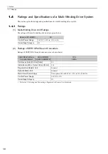
∗1.
Set Pn001 to
2 in the multi-winding drive unit parameters if you will not use the dynamic brake.
∗2.
Implement risk assessment and confirm that the safety requirements of the machine have been met.
1.4.3
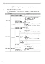
Speed/Position/Torque Control
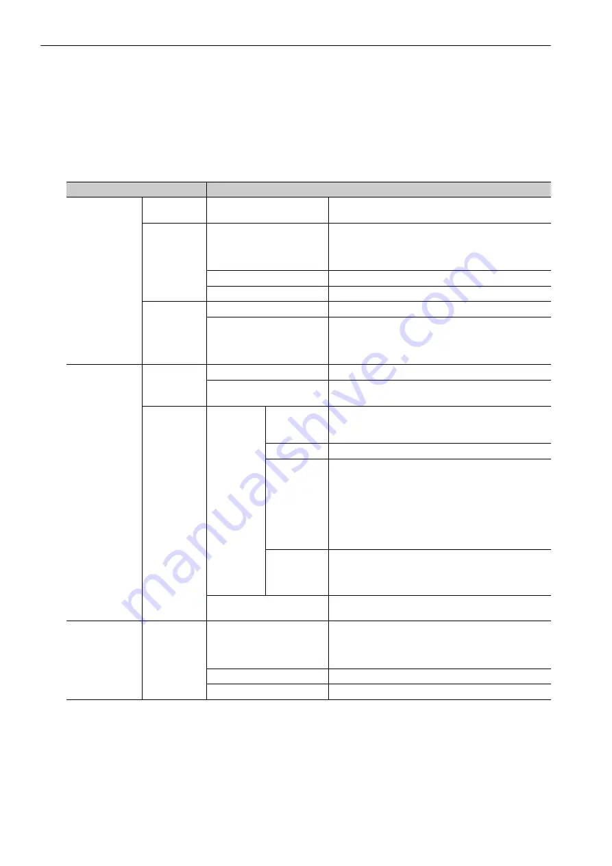
The following table shows the basic specifications of the multi-winding drive unit at speed/position/torque
control.
Control Method
Specifications
Speed Control
Performance
Soft Start Time Setting
0 to 10 s (Can be set individually for acceleration and
deceleration.)
Input Signals
Reference Voltage
• Max. input voltage
: ±
12 V
(forward speed reference with positive reference)
• Factory setting: 6 VDC at rated speed
Input gain setting can be varied.
Input Impedance
Approx. 14 k
Ω
Circuit Time Constant
30
μ
s
Internal Set
Speed Control
Rotation Direction Selection
With P control signal
Speed Selection
With forward/reverse external torque limit signal (speed 1
to 3 selection).
Servomotor stops or another control method is used when
both are OFF.
Position Control
Performance
Feedforward Compensation
0% to 100%
Positioning Completed
Width Setting
0 to 1073741824 reference units
Input Signals
Reference
Pulse
Type
Select one of them:
Sign + pulse train, CW + CCW pulse train, or two-phase
pulse train with 90
°
phase differential
Form
For line driver, open collector
Max. Input
Pulse Fre-
quency
Line driver
Sign + pulse train, CW + CCW pulse train: 4 Mpps
Two-phase pulse train with 90
°
phase differential:
1 Mpps
Open Collector
Sign + pulse train, CW + CCW pulse train: 200 kpps
Two-phase pulse train with 90
°
phase differential:
200 kpps
Reference
Pulse Input
Multiplication
Switching
1 to 100 times
Clear Signal
Position error clear
For line driver, open collector
Torque Control
Input Signals
Reference Voltage
• Max. input voltage
: ±
12 V
(forward torque reference with positive reference)
• Factory setting: 3 VDC at rated torque
Input gain setting can be varied.
Input Impedance
Approx. 14 k
Ω
Circuit Time Constant
16
μ
s

