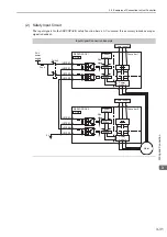
3.5 Examples of Connection to Host Controller
3-33
3
Wi
ring and
C
onne
ctio
n
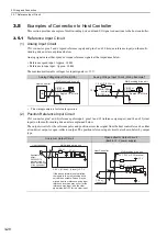
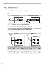
Photocoupler Output Circuit
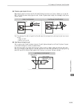
Photocoupler output circuits are used for the multi-winding drive unit’s servo alarm (ALM), servo ready (/S-
RDY), and other sequence output signal circuits. Connect a photocoupler output circuit through a relay or line
receiver circuit.
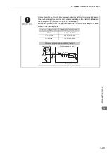
Note: The maximum allowable voltage and the allowable range of current capacity for photocoupler output circuits are as
follows.
• Voltage: 30 VDC
• Current: 5 to 50 mA DC
Line Driver Output Circuit
CN1 connector pins 33 and 34 (phase-A signal), 35 and 36 (phase-B signal), and 19 and 20 (phase-C signal)
on the multi-winding drive unit are explained below.
The following signals are output on the line-driver output circuit: 1) 0utput signals for which encoder serial
data is converted to two-phase (phases A and B) pulses (PAO, /PAO, PBO, and /PBO) and 2) origin pulse sig-
nals (PCO and /PCO). Receive these outputs with a line receiver circuit at the host controller.
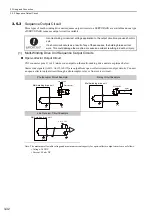
Relay Circuit Example
Line Receiver Circuit Example
0 V
Relay
5 to 24 VDC
Multi-winding drive unit
Multi-winding drive unit
5 to 12 VDC
Line Receiver Circuit Example
Multi-winding
drive unit
Host Controller
Applicable line receiver:
SN75ALS175 or the
equivalent
220 to
470
Ω


