5 Installation Procedure
18
YASKAWA ELECTRIC
TOBP C730600 35B YASKAWA AC Drive Option LED Operator Installation Manual
NOTICE:
Prevent foreign matter such as metal shavings or wire clippings from falling into the drive during
installation and project construction. Failure to comply could result in damage to the drive. Place a
temporary cover over the top of the drive during installation. Remove the temporary cover before startup, as
the cover will reduce ventilation and cause the drive to overheat.
■
External/Face-mount Installation
1.
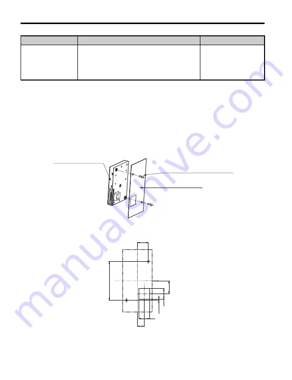
Cut an opening in the enclosure panel for the LED Operator Option according to
.
2.
Position the LED Operator Option so the LED display faces outwards, and mount
it to the enclosure panel as shown in
Figure 6
Figure 6 External/Face-mount Installation
Figure 7
Figure 7 Panel Cut-out Dimensions (External/Face-mount Installation)
Internal/Flush-mount
Encloses the LED Operator Option in the panel.
The LED Operator is flush with the outside of the
panel.
Requires purchase of
separate items.
Item Names and Part
Numbers (Sold
Separately) on page 10
Installation Method
Description
Notes
LED Operator Option
M3 × 6 (0.24)
Phillips recessed
pan head machine screw × 2
Enclosure panel
Unit: mm (in)
22 (0.87)
22(0.87)
14
(0.55)
Unit : mm (in)
26
(1.02)
22
(0.87)
78 (3.07)
2 (0.08)


