background image

Technical data

6

 - 

35

6.5.2

Stop category 1

The stopping angle and time at the emergency stop in category 1 are not subjected to the
robot position and the load.
Stop of category1 doesn't depend on the robot position and the load.

6.5.2.4

Stop position S-axis

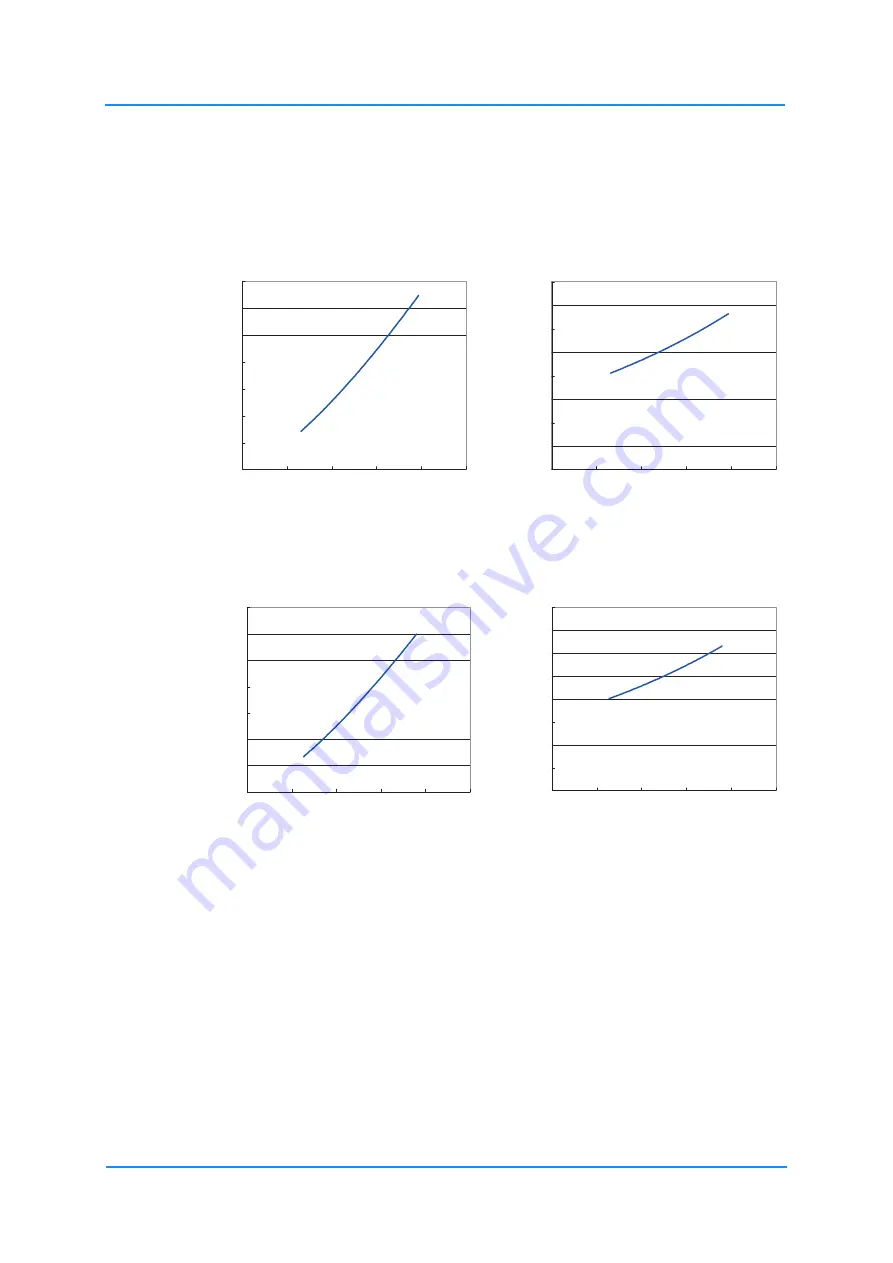
Fig. 6-14: Stop position

6.5.2.5

Stop position L-axis

Fig. 6-15: Stop position

[deg]

[deg/s]

[deg/s]

[sec]

㻝㻜

㻞㻜

㻟㻜

㻠㻜

㻡㻜

㻢㻜

㻣㻜

㻡㻜

㻝㻜㻜

㻝㻡㻜

㻞㻜㻜

㻞㻡㻜

㻜㻚㻝

㻜㻚㻞

㻜㻚㻟

㻜㻚㻠

㻜㻚㻡

㻜㻚㻢

㻜㻚㻣

㻜㻚㻤

㻡㻜

㻝㻜㻜

㻝㻡㻜

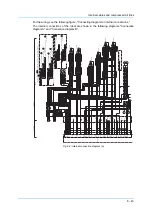
㻞㻜㻜

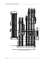
㻞㻡㻜

[deg]

[deg/s]

[deg/s]

[sec]

㻝㻜

㻞㻜

㻟㻜

㻠㻜

㻡㻜

㻢㻜

㻣㻜

㻡㻜

㻝㻜㻜

㻝㻡㻜

㻞㻜㻜

㻞㻡㻜
㻜㻚㻝

㻜㻚㻞

㻜㻚㻟

㻜㻚㻠

㻜㻚㻡

㻜㻚㻢

㻜㻚㻣

㻜㻚㻤

㻡㻜

㻝㻜㻜

㻝㻡㻜

㻞㻜㻜

㻞㻡㻜

Summary of Contents for MA2010

Page 1: ...YR MA02010 A10 Operating and maintenance instructions MA2010...

Page 2: ...iven in this publication is checked regularly and any necessary corrections will be made in subsequent editions Subject to technical modifications Created on 12 2014 Revision 4 Document number E110100...

Page 3: ...ling protective equipment 17 4 2 Location 18 4 3 Installation example 18 5 Wiring 22 5 1 Grounding 22 5 2 Cable connections 23 5 2 1 Connecting the robot 24 5 2 2 Connecting the robot control 25 5 2 3...

Page 4: ...gear unit 61 9 3 4 Grease replenishment exchange for R axis gear 62 9 3 5 Grease replenishment exchange for B and T axes gear 63 9 3 6 Replenishment Exchange for R axis cross roller bearings 65 9 4 H...

Page 5: ...NOTICE Indicates important background information and application advice 1 2 Frequently used terms The YASKAWA robot is a product of YASKAWA Electric Corporation and is provided by default with the ro...

Page 6: ...orting workpieces or products 1 5 Improper use Any use that deviates from the intended use shall be regarded as impermissible misuse This includes Transport of people and animals Use as ascending aid...

Page 7: ...rotective covers or shields removed All protective covers and shields must be mounted before the robot is operated The drawings and figures in this manual are representative illustrations They may dif...

Page 8: ...n 1 Short Cut Main Menu JOB CONTENT 0000 0001 0002 0003 0004 0005 0006 0007 0008 0009 0010 0011 TEST01 TOOL CONTROL GROUP R1 S 0000 NOP SET B000 1 SET B001 0 MOVJ VJ 80 00 MOVJ VJ 80 00 DOUT OT 10 ON...

Page 9: ...erating range of the robot View the Robot from the front whenever possible Always follow the prescribed operating procedure see the instructions on robot control as well as the operating instructions...

Page 10: ...anufacturer Address YASKAWA ELECTRIC CORPORATION 2 1 KUROSAKISHIROISHI YAHATANISHI KU KITAKYUSHU JAPAN 1 9 Authorized representative Address YASKAWA Europe GmbH Robotics Division Yaskawastr 1 85391 Al...

Page 11: ...ecking the scope of delivery The standard delivery includes the following items Fig 2 1 Scope of supply Programming pendant The present assembly instructions Robot controller Cable Robot MOTOMAN MANUA...

Page 12: ...NOTICE Please contact the local YASKAWA branch office if the serial numbers do not match the information on the delivery note S N DX200 YASAKAW DX200 Part No Power Supply Peak kVA AC 400 415 440 Aver...

Page 13: ...nal forces may be exerted on the robot controller 3 1 Transporting method CAUTION Damage to persons and damage to property due to external force influences External forces must not be exerted on the r...

Page 14: ...quate load handling devices must be used to transport the robot Make sure that the robot is lifted as shown in the diagram Transport by crane Fig 3 1 Transport with crane Shipping bracket and bolts 2...

Page 15: ...h transport securing devices and shipping bolts as shown in the figure below Transport using a forklift Make sure that the forklift and the transportation route have sufficient bearing capacity Always...

Page 16: ...sport securing devices and the shipping bolts keep them at a safe place The transport securing devices and shipping bolts will be required again if the system is transported again NOTICE Before turnin...

Page 17: ...protective devices Starting up without appropriate protective measures can lead to death of people serious bodily harm or damage to property Install following safeguardings Separating protection devic...

Page 18: ...sive vibration Vibration acceleration 4 9 m s 0 5 G or less Maximum unevenness of the support surface of the robot base 0 5 mm 4 3 Installation example 1 At the first setout anchor the baseplate firml...

Page 19: ...he base plate Screws at least 25 mm Spring washer Anchor bolt M16 or greater Washer 2 holes 12 H7 Robot base 4 holes 18 Base plate adhesive 25 1 2 3 4 5 6 4 7 10 375 60 316 200 0 1 260 0 1 170 0 1 375...

Page 20: ...Fig 4 3 Robot Force and Torque Horizontal direction Vertical direction Force FH Moment MH Force FV Moment MV Emergency stop 8820 N 6370 Nm 10290 N 13720 Nm Acceleration Deceleration 2940 N 1915 Nm 343...

Page 21: ...range is adjusted prior to the shipment B Axis operating range For ceiling mounted type the B axis operating range is 90 to 135 The range is adjusted prior to the shipment Fastening the robot base Wit...

Page 22: ...d wiring regulations for grounding The cable cross section must be 6 mm or more With regard to the direct connection of the earthing cable see Fig 5 1 Grounding method NOTICE Note on earthing connecti...

Page 23: ...he robot base and on the robot controller see the following chapter on robot connection and robot controller connection Fig 5 3 Robot cable Robot control side Encoder cable 1BC Robot side Power cable...

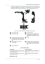
Page 24: ...he power cable 2BC 2 Connect the encoder cable 1BC to the connector plate of the robot 3 Connect the power cable 2BC to the connector plate of the robot Make sure that you hear each locking clip snap...

Page 25: ...wing order 1 Connect the encoder cable 1BC X11 connection X 1 to the robot controller 2 Connect the power cable 2BC X21 connection X 2 to the robot controller Make sure that you hear the locking clips...

Page 26: ...nt marks 1 X81 X81 PROGRAMMING PENDANT PROPERLY CHECK ALL THE DOOR LOCKS NJ3005 1 kVA kVA ERDR Average Peak NJ3053 1 Kammerfeldstr 1 D 85391 Allershausen 2 1 Kurosaki Shiroishi Yahatanishi Ku Kitakyus...

Page 27: ...st 210 210 Protection class IP Main axes 54 Wrist axis 67 Maximum speed S axis 3 44 rad s 197 s L axis 3 32 rad s 190 s U axis 3 67 rad s 210 s R axis 7 16 rad s 410 s B axis 7 16 rad s 410 s T axis 1...

Page 28: ...ing axes 6 2 Robot base dimension Fig 6 2 Robot base dimensions Upper arm U arm Rotating head of S axis Wrist Flange Robot base Lower arm L arm 4 mounting holes 18 Hole 12 H7 All dimensions in mm T T...

Page 29: ...P point The working area in which the robot can work with its wrist units B axis pointing downwards Working area defined with point P All dimensions in mm A R 5 6 1 139 95 495 229 266 157 3649 R2010...

Page 30: ...nt is the decisive axis movement for calculating the safety distance The values are shown for S L and U axes The values shown for stop category 0 are reference values determined through testing and si...

Page 31: ...sition of the robot axes Definitions Description Category 0 Load 100 pink Category 0 Load 66 green Category 0 Load 33 gray Category 1 blue Overrun distance degrees deg Overrun time second sec Robot sp...

Page 32: ...l data 6 32 6 5 1 Stop category 0 6 5 1 1 Stop position S axis Fig 6 5 Stop position 100 Fig 6 6 Stop position 66 Fig 6 7 Stop position 33 deg deg s deg s sec 100 deg deg s deg s sec 66 deg deg s deg...

Page 33: ...Technical data 6 33 6 5 1 2 Stop position L axis Fig 6 8 Stop position 100 Fig 6 9 Stop position 66 Fig 6 10 Stop position 33 deg deg s deg s sec 100 deg deg s deg s sec 66 deg deg s deg s sec 33...

Page 34: ...Technical data 6 34 6 5 1 3 Stop position U axis Fig 6 11 Stop position 100 Fig 6 12 Stop position 66 Fig 6 13 Stop position 33 deg deg s deg s sec 100 deg deg s deg s sec 66 deg deg s deg s sec 33...

Page 35: ...y stop in category 1 are not subjected to the robot position and the load Stop of category1 doesn t depend on the robot position and the load 6 5 2 4 Stop position S axis Fig 6 14 Stop position 6 5 2...

Page 36: ...Technical data 6 36 6 5 2 6 Stop position U axis Fig 6 16 Stop position deg deg s deg s sec...

Page 37: ...ore mounting a tool remove anticorrosive coating on the flange Thinner or light fuel oil are the most suitable for this purpose Fig 7 1 Wrist flange 7 2 Maximum load of the S axis For peripheral devic...

Page 38: ...ty load The maximum permissible load for U axis including wrist is 19 kg For example if the load mounted on the joint is 10 kg the load on the upper arm must not exceed 9 kg The maximum load for S axi...

Page 39: ...4 threaded holes M6 x 14 Mount the peripherals in this range 2 threaded holes M10 x 12 Mount the accessories so that the centre of gravity of the accessories is in the U arm within this range 2 threa...

Page 40: ...Connector for internal cables and compressed air lines The pins 1 to 16 are assigned as shown in the following figure Wiring must be performed by the user The following requirements must be met The t...

Page 41: ...mended connection R100 10 cover TS200CHM is included in the deliv ery Connector plug for the internal cable feedthrough JL05 2A20 29SC sock et connector with a cap JL05 6A20 29P View A Power cable fo...

Page 42: ...pective 3BC connections on the connector plate and U arm are connected to each other Internal wiring harness Section A A MA2010 A00 Welding power cable Section A MA2010 A10 assigned unassigned Connect...

Page 43: ...5 CN1 4 CN1 5 CN1 2 CN1 1 CN1 9 CN1 10 CN1 3 CN1 8 CN1 7 CN1 6 CN2 2 CN2 1 CN2 3 CN2 7 CN2 6 CN3 2 CN3 1 CN2 8 CN3 3 CN3 7 CN3 6 CN4 1 CN4 7 CN4 3 CN4 2 CN4 6 CN3 8 CN4 8 1BC 10X4 DATA 1 DATA 1 BAT 0...

Page 44: ...4 CN5 5 CN5 6 CN6 1 CN6 2 CN6 3 CN6 4 CN6 5 CN6 6 2BC 6X6 Note 2 E E E ME1 ME2 ME2 MU1 MV1 MW1 MV2 MU2 MW2 MW2 MU3 MV2 MU2 MW3 MV4 MU4 MV5 MU5 MW4 MU6 MW6 MV6 ME3 ME5 ME4 MW5 BA1 BA2 BB1 BA3 BA4 BB4 B...

Page 45: ...ng maintenance and inspection measures Turn OFF the main power supply Put up the warning sign prescribed e g Do not turn the power on Install a switch on guard as prescribed If you have any questions...

Page 46: ...UTILITY Main Menu ShortCut CONTROL POWER TIME 1998 07 06 10 00 2385 42 02 SERVO POWER TIME 1998 07 06 10 30 36000 00 00 PLAYBACK TIME 1998 10 22 11 12 2210 00 20 MOVING TIME 1998 10 22 15 30 1875 15...

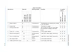
Page 47: ...External cable Visual inspection Check cable for damage 3 Working area and robot Visual inspection Dirty working area has to be cleaned Please control the robot for damage and external cracks 4 Motor...

Page 48: ...Replacement 11 Protective tube Visual inspection Inspect the protective tube for holes cracks and adhesion of welding spatters replace if neces sary Refer to manual OPTIONS FOR PROTECTIVE TUBING VELCR...

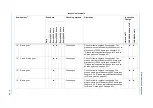
Page 49: ...ge for L axis re duction gear unit on page 60 15 R axis gear Grease gun Check for faults replace if necessary The grease has to be refilled every 6000 hours see chapter 9 3 4 Grease replenishment exch...

Page 50: ...filled every 6000 hours see chapter 9 3 5 10 Refilling grease at T axis gear on page 64 Inspection intervals Item number1 Schedule Checking method Operation Inspection Charge Daily Every 1000 hours Ev...

Page 51: ...observe this sequence can lead to loss of home positions see section 9 2 3 1 Wrist unit on page 58 3 The internal wiring harness in the robot for the S L U R B and T axes must be replaced at the 24 00...

Page 52: ...Maintenance and inspection 9 52 Fig 9 2 Inspection intervals The numbers in the above figure are equal to the numbers in the table of Inspection intervals 14 14 13 11 11 9 15 12 8 5 4 17 4 4 8...

Page 53: ...n of the battery unit If battery alarm occuring in the robot controller battery pack has to be changed in the following form Inspection parts and grease used No Grease Used Material no Inspected Parts...

Page 54: ...e plug from circuit board 4 Connect the new battery pack to the unoccupied connector on the board Fig 9 5 Battery pack connections 5 Remove the old battery pack from the battery holder 6 Mount the new...

Page 55: ...d NOTICE Make sure that no wires are pinched when you install the battery pack and the cover plate again 8 Please apply Teroson Plast sealing compound material no 143813 to thread part of screws Excha...

Page 56: ...Battery pack connector diagram for S L and U axes Before removing the encoder connector with CAUTION label connect the battery to the motor as shown in the following figure Motor Battery pack Motor po...

Page 57: ...Warning label Motor cable Power connector Battery pack Wiring harness of the robot a Plug socket b Plug pin Motor Encoder connector Connect battery to encoder to save the data before removing connecto...

Page 58: ...outlet If the plug is not removed grease will enter the motor or the oil seal of the gear will be damaged This might cause damage to the motor or gear Lubrication or grease replacement is only allowed...

Page 59: ...the plug Before mounting the plug apply Teroson Plast sealing compound material no 143813 to thread part 9 3 1 3 Replace grease See figure S axis gear diagram 1 Remove plug from grease exhaust port a...

Page 60: ...ug Before installing the plugs apply Teroson Plast sealing compound material no 143813 to thread part 9 3 2 5 Replace grease See figure L axis gear diagram 1 Remove plug from grease exhaust port and g...

Page 61: ...reinstall the plug Before installing the plugs apply Teroson Plast sealing compound material no 143813 to thread part 9 3 3 7 Replace grease See figure U axis gear diagram 1 Remove plug from grease ex...

Page 62: ...se inlet port 2 Install lubricating nipple to grease inlet port 3 Squeeze grease by grease gun in grease inlet port Amount of grease 12 cm approx 10 g 4 Move R axis for a few minutes to discharge exce...

Page 63: ...Install lubricating nipple to grease inlet port 3 Squeeze grease by grease gun in grease inlet port Amount of grease 6 cm approx 5 g 4 Wipe away excess grease with a cloth Remove the grease zerk from...

Page 64: ...et port 3 Squeeze grease by grease gun in grease inlet port Amount of grease 11 cm approx 10 g 4 Move T axis gear for a few minutes to discharge excess grease 5 Wipe away excess grease with a cloth Re...

Page 65: ...y grease gun in grease inlet port Amount of grease 45 cm 40 g 4 Move R axis gear for a few minutes to discharge excess grease 5 Wipe away excess grease with a cloth Remove the grease zerk from the gre...

Page 66: ...te encoder must match it Although this operation is performed prior to shipment at the factory the following cases require this operation to be performed again Change in the combination of the robot a...

Page 67: ...Maintenance and inspection 9 67 9 4 1 Register all axes 1 Select ROBOT from the main menu The sub menu choices appear 2 Select HOME POSITION The HOME POSITIONING window appears...

Page 68: ...3 can also be performed by selecting the PAGE button In this case a selection box appears 4 Select the sub assembly to calibrate e g R1 ROBOT Select the control group for HOME POSITIONING The control...

Page 69: ...the main menu The sub menu choices appear 2 Select HOME POSITION 3 Select the sub assembly to calibrate e g R1 ROBOT Carry out steps 3 and 4 as described in section 9 4 1 Register all axes on page 67...

Page 70: ...e 67 to select the desired control group 4 Select the absolute data to be registered 5 Enter the absolute data using the numeric keys 6 Select ENTER The absolute encoder data is changed 9 4 4 Clearing...

Page 71: ...check operation If the absolute number of rotations determined at power supply ON does not match the data stored in the absolute encoder the last time the power supply was turned OFF an error message...

Page 72: ...eck point pulses with current po sition pulses alarm reset Alarm occurs again SERVO ON power ON Correct the faulty axis replace the pulse generator system set the home position Procedure after alarm P...

Page 73: ...pulse generator system Check the pulse generator system After adjusting the faulty axis calibrate the home position of the axis then check the position again NOTICE Home position calibration of all a...

Page 74: ...oken Available to move to and modify specified point 3 Press the page key or select PAGE to display the selection window for the control group Occuring 2 or more group axes select those one to you int...

Page 75: ...sition After the confirmation if the PG system is found to be the cause of the alarm perform the necessary operation such as replacing the PG system etc The robot current position data when turning ma...

Page 76: ...cted manual speed 5 Select DATA in the menu 6 Select CONFIRM POSITION A message Home position checked appears Pulse data of the second home position and current pulse data should be compared Automatic...

Page 77: ...acement parts List of recommended spare parts for stocking Category Description Type Material no Qty Qty per unit A Grease Molywhite RE No 0 100274 16 kg A Grease Harmonic grease SK1A 127610 2 5 kg A...

Page 78: ...ot HW1171441 A 1 1 B Internal wiring harness for B and T axes HW1271107 A 1 1 C S axis motor HW0388665 A SGMRV 09ANA YR1 E144076 1 1 C L axis motor HW0388666 A SGMRV 13ANA YR1 1 1 C U axis motor HW038...

Page 79: ...1007 1006 1005 1010 1022 1001 1023 1009 1013 1002 1003 1004 1015 1024 1027 1027 1016 1019 1020 1008 1012 1014 1011 1026 1044 1030 1017 1018 1021 1045 1046 1046 1046 1045 1031 1028 1025 1029 1038 1039...

Page 80: ...ANA YR1 Motor 1 1015 M12 x 45 Screw 8 1016 2H 12 Washer 8 1017 TSH8 03 Link 1 1018 NB 0860 Hose 1 1019 MSB8 15 Screw 1 1020 HW0400645 3 Plug 1 1021 TSH8 03 Support 1 1022 HW1304380 1 Cover 1 1023 M6 x...

Page 81: ...11 1 S axis drive 1039 2H 5 Washer 4 1040 HW1405589 1 Support 1 1041 TA1 S10 Terminal 1 1042 M5 x 8 Screw 1 1043 T50R Cable tie 1 1044 C 30 SG 30A Cover 1 1045 KQ2L08 00 Link 2 1046 NB 0860 Hose 3 No...

Page 82: ...04 2H 6 Washer 1 2005 M12 x 40 Screw 12 2006 2H 12 Washer 12 2007 M10 x 35 Screw 6 2008 2H 10 Washer 6 2009 M12 x 35 Screw 2 2010 HW1405429 1 Washer 2 2011 HW0387753 G Gear box 1 2012 M10 x 40 Screw 1...

Page 83: ...6 SGMRV 13ANA YR1 Motor 1 2017 Y426012 5 Oil seal 1 2018 M8 x 25 Screw 4 2019 PT1 8 Set screw 2 2020 PT3 8 Set screw 1 2021 NPTF3 8 Set screw 1 2022 HW1405456 1 Cover 1 2023 M6 x 15 Screw 4 2024 HW140...

Page 84: ...s lists 11 84 11 3 U axis drive Fig 11 3 U axis drive 3001 2001 3014 3006 3007 3002 3002 3005 3008 3003 3004 3009 3011 3021 3018 3019 3028 3027 3026 3020 3017 3012 3013 3015 3016 3023 3022 3025 3029 3...

Page 85: ...x 35 Screw 16 3011 M5 x 16 Screw 3 3012 M8 x 40 Screw 18 3013 2H 8 Washer 18 3014 SGMRV 05ANA YR1 Motor 1 3015 M8 x 30 Screw 4 3016 PT3 8 Set screw 1 3017 M4 X 12 Screw 3 3018 HW1405434 1 Cover 1 3019...

Page 86: ...4026 4009 4010 4013 4055 4063 4054 4057 4007 4017 4032 4048 4037 4046 4049 4040 4018 4015 4008 4014 4027 4021 4022 4036 4019 4059 4062 4011 4012 4023 3001 5063 4020 4024 4025 4041 4047 4052 4050 4053...

Page 87: ...TC20305 FKM Oil seal 1 4016 M3 x 12 Screw 6 4017 HW1405390 1 Housing 1 4018 HW1304320 1 Pinion 1 4019 M4 X 14 Screw 1 4020 2H 4 Washer 1 4021 M3 x 12 Screw 4 4022 M4 X 12 Screw 4 4023 M4 X 12 Screw 4...

Page 88: ...W1303904 1 Cover 1 4050 M4 X 12 Screw 7 4051 HW9481319 D Cable feedthrough 1 4052 M4 X 12 Screw 1 4053 M4 X 12 Screw 2 4054 HW1200341 1 Spacer 1 4055 HW1405367 1 Cover 1 4056 M4 X 10 Screw 10 4057 MST...

Page 89: ...1 5025 5020 5019 5021 5022 5005 5005 5018 5040 5005 5009 5008 5016 5056 5009 5023 5052 5055 5064 5029 5031 5033 5032 5034 5005 5030 5051 5049 5053 5028 5050 5054 5048 5005 5035 5024 5060 5061 5014 501...

Page 90: ...19 Toothed belt 1 5018 WR20 Terminal 1 5019 HW1303260 1 Shaft 1 5020 HW1404049 1 Cover 1 5021 M8 x 40 Screw 1 5022 2H 8 Washer 1 5023 HW1481728 A Bearing 1 5024 6809DDU Bearing 1 5025 HW1404059 6 Spri...

Page 91: ...03LLU Bearing 1 5052 HW1404037 A Pulley 1 5053 M3 x 16 Screw 4 5054 HW1404047 1 Housing 1 5055 HW1382522 A Gear box 1 5056 60S3M642 Toothed belt 1 5057 HW1303243 1 Cover 1 5058 SGMAV 01ANA YR1 Motor 2...

Page 92: ...Parts list gear unit No DWG no Designation Pcs 6001 HW1303251 1 Gear box 1 6002 HW1303252 1 Gear box 1 6003 HW1404051 1 Sleeve 2 6004 HW1404050 1 Pin 6 6005 WB5 30 Clamping sleeve 3 6006 M3 x 12 Scre...

Page 93: ...Parts lists 11 93...

Page 94: ...TR YASKAWA Turkey Elektrik Ticaret Ltd Sti stanbul 90 216 5273450 ZA YASKAWA Southern Africa PTY Ltd Johannesburg 27 11 6083182 Distributors BG Kammarton Bulgaria Ltd Sofia 359 02 926 6060 CH Messer...

Reviews: