background image

1-1

1

Overview

1

Overview

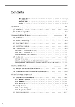
1.1 Outline - - - - - - - - - - - - - - - - - - - - - - - - - - - - - - - - - - - - - - - - - - - - - - - - - 1-2

1.2 System Configuration  - - - - - - - - - - - - - - - - - - - - - - - - - - - - - - - - - - - - - - 1-3

Summary of Contents for MECHATROLINK-III

Page 1: ...Network Adapter MECHATROLINK III Compatible USER S MANUAL MANUAL NO SIEP C880781 07A 1 2 3 4 Overview Adapter Unit Specifications Connection Method Operation of the Adapter Tool...

Page 2: ...liability is assumed with respect to the use of the information contained herein Moreover because Yaskawa is con stantly striving to improve its high quality products the information contained in this...

Page 3: ...product may fail to operate normally Indicates supplemental information Indicates application examples Describes technical terms that are difficult to understand or appear in the text without an expl...

Page 4: ...injury Indicates precautions that if not heeded could result in relatively serious or minor injury damage to the product or faulty operation In some situations the precautions indicated could have se...

Page 5: ...damage WARNING Do not store or install the Adapter Unit in locations subject to the following conditions There is a risk of fire electrical shock or device damage Direct sunlight Ambient temperature e...

Page 6: ...ere is a risk of an accident CAUTION Check the wiring to be sure it has been performed correctly There is a risk of motor overrun injury or an accident Always use a power supply of the specified volta...

Page 7: ...les Digital I O signal cables Do not attempt to disassemble the MECHATROLINK device There is a risk of electrical shock or injury Do not change wiring while power is being supplied There is a risk of...

Page 8: ...product in a manner in which it was not originally intended 5 Causes that were not foreseeable with the scientific and technological understanding at the time of ship ment from Yaskawa 6 Events for wh...

Page 9: ...property Systems that require a high degree of reliability such as systems that supply gas water or electricity or systems that operate continuously 24 hours a day Other systems that require a similar...

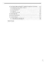
Page 10: ...when Errors Occur 2 6 2 6 Connectors 2 7 2 6 1 List of Connectors 2 7 2 6 2 Connector Specifications for MECHATROLINK Connections 2 7 2 6 3 Specifications of the Connector for Ethernet Transmission wi...

Page 11: ...2 List of Main Menu Options 4 19 4 4 3 List of Toolbar Icons 4 20 4 4 4 Caption Bar 4 20 4 4 5 Slave Device List Window 4 21 4 5 Self Configuration 4 22 4 6 Saving to Flash Memory 4 23 4 7 Version Inf...

Page 12: ...1 1 1 Overview 1 Overview 1 1 Outline 1 2 1 2 System Configuration 1 3...

Page 13: ...address vendor ID and device ID of the devices connected to the MECHATROLINK III can be checked Network Adapter can be connected to MECHATROLINK III communication Since Network Adapter functions as a...

Page 14: ...Adapter Unit at a terminal of the MECHATROLINK III network Fig 1 1 System Configuration Example with MECHATROLINK III Network Since the Adapter Unit functions as the C2 master station in the network t...

Page 15: ...ons 2 5 2 5 LED Indicators 2 6 2 5 1 Indicators for the Adapter Tool PC 2 6 2 5 2 Indicators for the Network 2 6 2 5 3 LED Indications when Errors Occur 2 6 2 6 Connectors 2 7 2 6 1 List of Connectors...

Page 16: ...2 Adapter Unit Specifications 2 2 2 1 Appearance The following shows the appearance of the Adapter Unit Indicators LED Switch MECHATROLINK connector MECHATROLINK connector Ethernet connector...

Page 17: ...nsional Drawing 2 3 2 Adapter Unit Specifications 2 2 Dimensional Drawing The following shows the dimensional drawing of the Adapter Unit Nameplate Power connector 3 pins 721 203 026 000 Unit mm 45 13...

Page 18: ...ondensation Storing Ambient Humidity 5 to 95 RH with no dew condensation Pollution Level Conforming to JIS B 3502 pollution level 2 Corrosion Resistance There should be no flammable or corrosive gas O...

Page 19: ...d by the system Always set to OFF OFF OFF 2 E INIT ON Default Ethernet transmission parameters Sets the transmission parameters such as the IP address to the default values at startup OFF OFF Normal o...

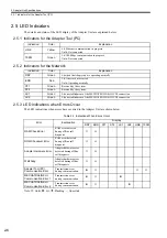
Page 20: ...rror has occurred Unlit Operating normally ST1 Green Reserved by the system ST2 Green Reserved by the system LK1 Green Lit on establishment of the MECHATROLINK III CN1 connection LK2 Green Lit on esta...

Page 21: ...d Grounding CN1 and CN2 for MECHATROLINK III Connection 1 TXP Sent data positive side 2 TXN Sent data negative side 3 RXP Received data positive side 4 5 6 RXN Received data negative side 7 8 CN4 for...

Page 22: ...03 E 3 0 m JEPMC W6012 04 E 4 0 m JEPMC W6012 05 E 5 0 m JEPMC W6012 10 E 10 m JEPMC W6012 20 E 20 m JEPMC W6012 30 E 30 m JEPMC W6012 50 E 50 m Connectors manufactured by Tyco Electronics AMP K K on...

Page 23: ...The pin arrangement of the Ethernet connector is shown in the following table 3 Indicators Name Connector Name Number of Pins Connector Type Unit Side Cable Side Manufacturer Ethernet Ethernet 8 RJ 45...

Page 24: ...3 1 3 Connection Method 3 Connection Method 3 1 MECHATROLINK Terminal Connection 3 2 3 2 Connection with a MECHATROLINK Hub Module 3 3...

Page 25: ...on If reconnecting the Adapter Unit when the power is ON hot swapping set the number of retries for the master station to three or more MECHATROLINK III Ethernet PC Adapter Tool Adapter Unit C1 master...

Page 26: ...connection with a Hub Module is shown below If reconnecting the Adapter Unit when the power is ON hot swapping set the number of retries for the master station to three or more MECHATROLINK III Hub Mo...

Page 27: ...nstallation 4 2 4 1 3 Uninstallation 4 6 4 2 Setting Ethernet 4 9 4 2 1 IP Address Setting 4 9 4 2 2 Changing the IP Address 4 14 4 3 Starting and Quitting 4 17 4 4 Operating the MECHATROLINK III ADAP...

Page 28: ...igher or equivalent 1 GHz or higher recommended Memory Capacity 128 MB or greater 256 MB or greater recommended Display Resolution 1024 768 or better 16 bit High Color Available Disk Space 200 MB min...

Page 29: ...n example Prepare the CD ROM for installing the Adapter Tool and proceed as follows 1 Start the PC and set the installation CD ROM in the CD ROM drive The installer of the Adapter Tool automatically s...

Page 30: ...n destination setting window appears 4 If you want to install the software in the folder displayed as the destination folder click Next To install the software in another folder click Browse and speci...

Page 31: ...Click Install Installation starts and messages that show its progress are displayed as it proceeds The installation com pletion window appears when installation is completed 6 Click Finish The instal...

Page 32: ...dure is explained here by taking Windows XP as an example 1 Quit the Adapter Tool and open the Windows Control Panel 2 Click the Add or Remove Programs icon The Add or Remove Programs window appears O...

Page 33: ...A MECHATROLINK III ADAPTER Configuration Tool from the list of installed programs and click Remove A dialog box confirming removal of the program appears 4 Click OK Uninstallation of the Adapter Tool...

Page 34: ...4 Operation of the Adapter Tool 4 1 3 Uninstallation 4 8 5 Click Finish The Add or Remove Programs window appears again 6 Click the close button to close the Add or Remove Programs window...

Page 35: ...ss settings at the PC in order to connect the Adapter Unit and the PC in which the Adapter Tool has been installed via a LAN cable Setting the Ethernet IP address to 192 168 1 x Fig 4 1 Example of Con...

Page 36: ...le 1 Connect a LAN cable to the Adapter Unit and the PC running the Adapter Tool 2 Set the IP address of the PC to 192 168 1 2 a Open the Windows Control Panel and click the Internet Options icon The...

Page 37: ...dows Control Panel and doubleclick the Network Connections icon The Network Connections window appears e Right click the Local Area Connection and select Properties from the popup menu displayed The L...

Page 38: ...se the following IP address checkbox and enter the IP address 192 168 1 2 at IP address and the subnetmask 255 255 255 0 at Subnet mask h Click OK to close the Internet Protocol TCP IP Properties dial...

Page 39: ...onfiguration Tool to start the Adapter Tool The MECHATROLINK III ADAPTER Configuration Tool window appears b Select Setting Ethernet Setting from the main menu The Communications Setting dialog box ap...

Page 40: ...king Windows XP as an example 1 In this explanation it is assumed that the IP address of the PC is set to 192 168 1 2 and that of the Adapter Unit to 192 168 1 1 2 Change the IP address of the Adapter...

Page 41: ...ion Tool window 5 Change the DIP switch setting of the Adapter Unit to start from the flash memory Change the DIP switch setting of the Adapter Unit to start from the flash memory by setting the 5th p...

Page 42: ...ties from the popup menu displayed c Select Internet Protocol TCP IP from the list and click Properties The Internet Protocol TCP IP Properties dialog box appears d Check the Use the following IP addr...

Page 43: ...YE_Applications MECHATROLINK III ADAPTER Configu ration Tool To quit the Adapter Tool select File Exit from the main menu or click the close button of the MECHA TROLINK III ADAPTER Configuration Tool...

Page 44: ...olbar Used to select functions provided to operate the Adapter Tool e Caption bar Displays the connection status online offline and the communication port at online state of the Adapter Unit f Connect...

Page 45: ...u Option Explanation Toolbars Standard Switches the display hide status of the toolbar Customize Customizes the toolbar and the menus Status Bar Switches the display hide status of the status bar Menu...

Page 46: ...ed 2 When Online In the online state the communication port and the IP address of the connected Adapter Unit are displayed Icon Name Explanation Connection Connects to the Adapter Unit Disconnection D...

Page 47: ...Y extended address Vender ID Vender name Displays the vendor name of the slave devices The vendor ID is displayed in hexadecimal format When the vendor name cannot be determined from the vendor ID onl...

Page 48: ...atically be identified 1 Select Adapter Self Configuration from the main menu The Self Configuration dialog box appears 2 Click Start Self configuration starts When the process is completed a dialog b...

Page 49: ...f data to the flash memory starts When the process is completed the dialog prompting normal completion of saving to the flash memory appears 3 Click OK 4 Close the MECHATROLINK III ADAPTER Configurati...

Page 50: ...ation 4 7 1 Version Information of the Adapter Unit To display the version information of the Adapter Unit select Help M III ADAPTER Version from the main menu 4 7 2 Version Information of the Adapter...

Page 51: ...o Section Revised Contents April 2018 2 0 2 3 Revision Noise resistance January 2018 1 0 Front cover Revision Format 2 3 Revision Pollution Level Noise Resistance Back cover Revision Address and forma...

Page 52: ...2 017 0099 Fax 66 2 017 0799 http www yaskawa co th YASKAWA ELECTRIC CHINA CO LTD 22F One Corporate Avenue No 222 Hubin Road Shanghai 200021 China Phone 86 21 5385 2200 Fax 86 21 5385 3299 http www ya...

Reviews: