6 Parameter Setting and Functions
6.2.6 Parameter Settings
6-14
Electronic Gears
For information on the parameters, refer to
6.3.2 Electronic Gear Function
.
Reverse Rotation Settings
The settings shown in the following table must be made in order to use the Reverse Rotation
Mode.
If this settings are not correct, improper axis control may lead to motor overrun. Confirm
the operation carefully.
* 1. This setting is for when Reverse Rotation Mode is not being used.
* 2. This setting is for when Reverse Rotation Mode is being used.
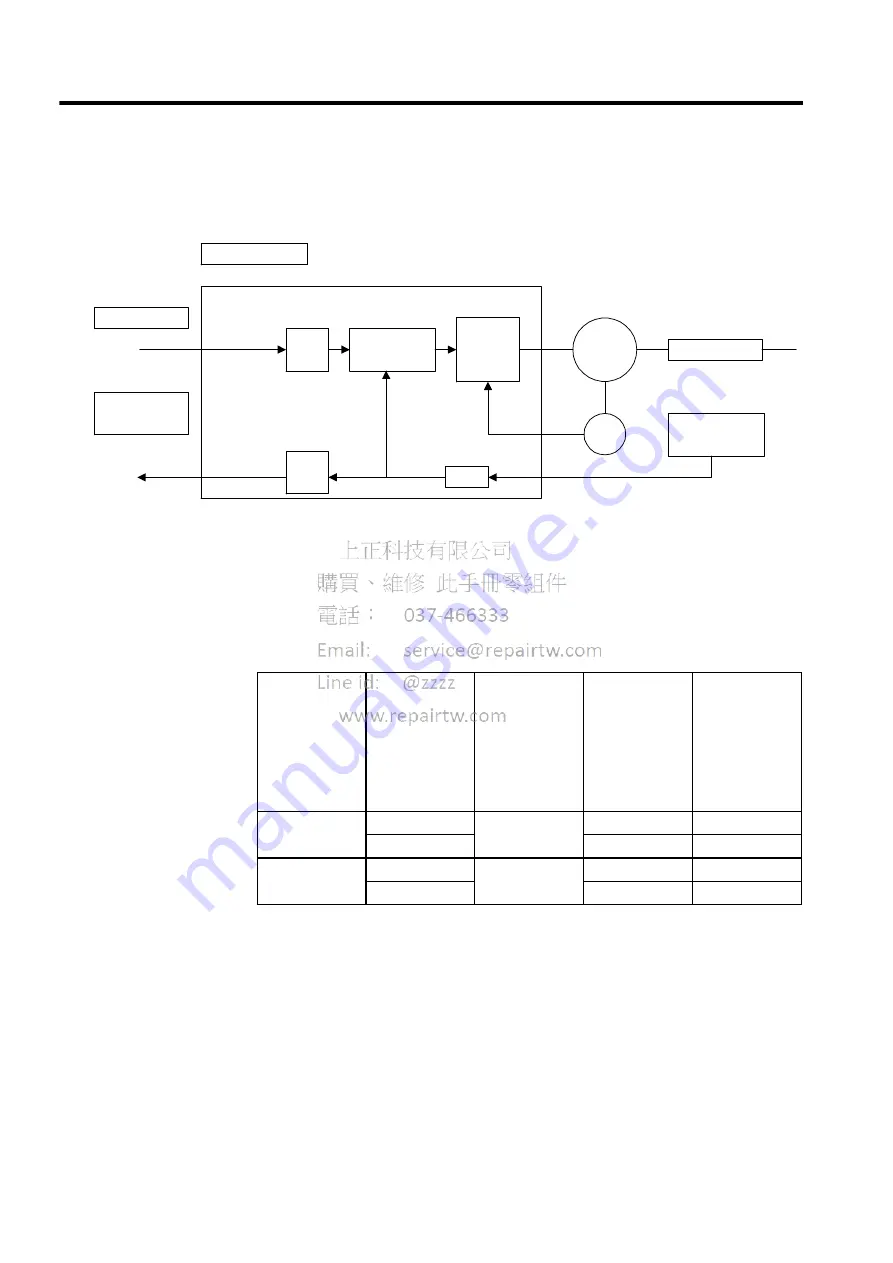
Elec-
tronic
gear
Deviation
counter
Speed
current
loop
Position reference
Encoder posi-
tion output
Machine
Fully closed PG
PG
SERVOPACK
Servo-
motor
×
4
Elec-
tronic
gear
Direction of
Motor as
Viewed from
Load for
Forward
Rotation
Relation
between Fully
Closed PG
during Forward
Rotation Input
Phase
Pn000.0 Setting Pn002.3 Setting
Relation
Between Fully
Closed PG
during CCW
Rotation as
Viewed from
Motor load Input
Phase
CCW direction
∗
1
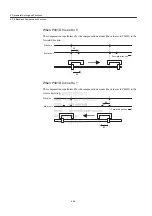
Figure 6.2
0
1, 2
Figure 6.2
Figure 6.3
3, 4
Figure 6.3
CW direction
∗
2
Figure 6.2
1
1, 2
Figure 6.3
Figure 6.3
3, 4
Figure 6.2


