6 Parameter Setting and Functions
6.3.1 Sequence I/O Signals
6-16
6.3 Settings According to Host Controller
This section describes the procedure for connecting a
Σ
-
ΙΙ
Series Servo to a host controller,
including the procedure for setting related parameters.
6.3.1 Sequence I/O Signals
Sequence I/O signals are used to control SERVOPACK operation. Connect these signal ter-
minals as required.
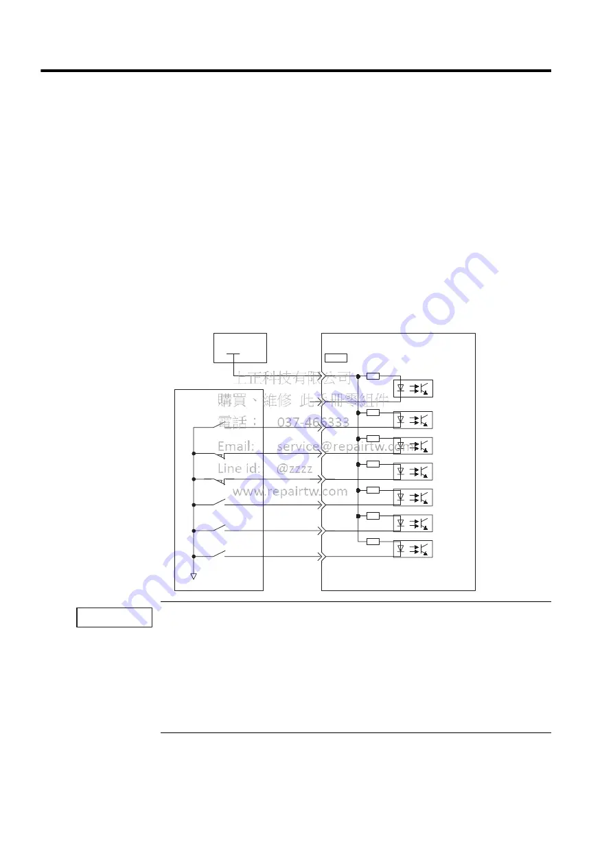
Input Signal Connections
Connect the sequence input signals as shown below. (Standard settings)
Provide an external input power supply; the SERVOPACK does not have an internal 24-V power sup-
ply.
• External power supply specifications for sequence input signal: 24
±
1 VDC, 50 mA min.
Yaskawa recommends using the same external power supply as that used for output circuits. The
allowable voltage range for the 24-V sequence input circuit power supply is 11 to 25 V. Although a 12-
V power supply can be used, contact faults can easily occur for relays and other mechanical contacts
under low currents. Confirm the characteristics of relays and other mechanical contacts before using a
12-V power supply.
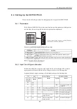
The function allocation for sequence input signal circuits can be changed.
Refer to
6.4.2 Input Circuit Signal Allocation
for more details.
I/O power
supply
SERVOPACK
Photocoupler
Host controller
47
40
41
+24V
42
43
44
45
46
0 V
+24VIN
CW-OT
CCW-OT
/EXT2
/EXT1
/DEC
/EXT3
3.3k
Ω
CN1
IMPORTANT


