6 Parameter Setting and Functions
6.4.4 Monitoring
6-36
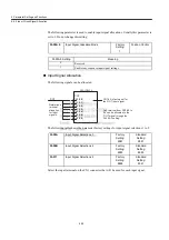
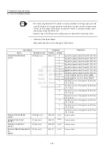
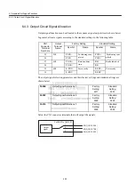
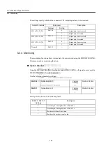
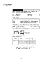
The settings specify which of the connector CN1 output signals are to be reversed.
6.4.4 Monitoring
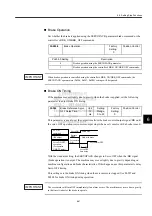
The monitoring function allows various data to be monitored using the MECHATROLINK-
II communications monitoring function.
Option Monitor
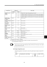
Using the MECHATROLINK-II option monitor (OMN1, OMN2), all signals not covered by
MECHATROLINK-II can be monitored.
Use the following parameter settings.
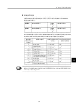
Settings are as shown in the following table.
Output Terminals
Parameter
Description
Number
Setting
SO1 (CN1-25, 26)
Pn512.0
0
Output signal not reversed.
1
Output signal reversed.
SO2 (CN1-27, 28)
Pn512.1
0
Output signal not reversed.
1
Output signal reversed.
SO3 (CN1-29, 30)
Pn512.2
0
Output signal not reversed.
1
Output signal reversed.
Not used.
Pn512.3
−
−
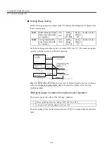
Pn813.0
Option Monitor 1
Factory
Setting:
0
Position Control
Pn813.1
Option Monitor 2
Factory
Setting:
1
Position Control
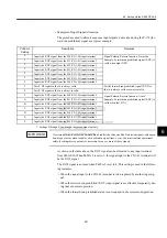
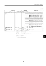
Pn813.0, Pn813.1
Settings
Description
0
According to Analog Monitor 1 (Pn003.0).
1
According to Analog Monitor 2 (Pn003.1).
2
Monitors initial multiturn data.
3
Monitors the encoder count value.


