background image

9  Troubleshooting


9-4

„

A.81

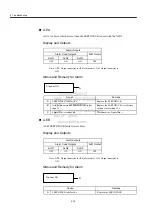
A.81: Encoder Backup Error

Display and Outputs

Note: OFF:  Output transistor is OFF (alarm state).

Status and Remedy for Alarm

Alarm Outputs

Alarm Code Outputs

ALM Output

ALO1

ALO2

ALO3

OFF

OFF

OFF

OFF

Cause

Remedy

A

The following power supplies to the absolute 
encoder all failed:

• +5 V supply (supplied from the 

SEROVPACK)

• Battery power

Follow absolute encoder set-up procedure.

B

Absolute encoder malfunctioned.

Replace the servomotor.

C

Circuit board (1PWB) is defective.

Replace the SERVOPACK.

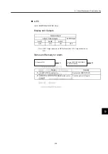
At power ON

Pn002.2 = 0

Pn002.2 = 1

A, B, C

C

At SENS_ON command

A, C

Summary of Contents for MECHATROLINK Sigma 2 Series

Page 1: ...YASKAWA MANUAL NO SIEP C710800 01C YASKAWA MECHATROLINK APPLICATION MODULE USER S MANUAL Series SGDH MODEL JUSP NS115...

Page 2: ...liability is assumed with respect to the use of the information contained herein Moreover because Yaskawa is con stantly striving to improve its high quality products the information contained in this...

Page 3: ...LINK II Those designing II Series servodrive systems Those installing or wiring II Series servodrives Those performing trial operation or adjustments of II Series servodrives Those maintaining or insp...

Page 4: ...he following aids are used to indicate certain types of information for easier reference Indicates application examples Indicates supplemental information Indicates important information that should b...

Page 5: ...tors and capacities and detailed information on installation wiring trial operation using functions maintenance and inspection Series SGM H SGDM Digital Operator Operation Manual TOE S800 34 Provides...

Page 6: ...damage to the product or faulty operation Even items described in may result in a vital accident in some situ ations In either case follow these important notes Indicates actions that must never be ta...

Page 7: ...products in an environment subject to water corrosive gases inflammable gases or combustibles Doing so may result in electric shock or fire Connect the ground terminal to electrical codes ground resis...

Page 8: ...Before starting operation with a machine connected make sure that an emergency stop can be applied at any time Not doing so may result in injury Do not touch the heat sinks during operation Doing so m...

Page 9: ...subject to change due to product improvement specification modification and manual improvement When this manual is revised the manual code is updated and the new manual is published as a next edition...

Page 10: ...3 3 I O Signals 3 6 3 3 1 Connection Example of I O Signal Connector CN1 3 6 3 3 2 I O Signals Connector CN1 3 7 3 3 3 I O Signal Names and Functions 3 8 3 3 4 Interface Circuits 3 9 3 4 Fully Closed...

Page 11: ...D 1BH 4 18 4 3 12 Write Non volatile Parameter PPRM_WR 1CH 4 19 4 3 13 Set Coordinates POS_SET 20H 4 20 4 3 14 Apply Brake BRK_ON 21H 4 21 4 3 15 Release Brake BRK_OFF 22H 4 22 4 3 16 Turn Sensor ON S...

Page 12: ...g 4 62 4 6 1 Command Data Execution Timing 4 62 4 6 2 Monitor Data Input Timing 4 62 4 7 Operation Sequence 4 63 4 7 1 Operation Sequence for Managing Parameters Using a Controller 4 63 4 7 2 Operatio...

Page 13: ...7 6 4 Setting Up the SERVOPACK 6 29 6 4 1 Parameters 6 29 6 4 2 Input Circuit Signal Allocation 6 29 6 4 3 Output Circuit Signal Allocation 6 34 6 4 4 Monitoring 6 36 6 5 Setting Stop Functions 6 38 6...

Page 14: ...ommand List A 2 A 2 MECHATROLINK II Command Format List A 5 Appendix B List of Parameters B 1 Parameters B 2 B 2 Function Switches B 9 Appendix C Using the Adjusting Command ADJ 3EH C 1 Autotuning C 2...

Page 15: ...ames This chapter describes the procedure for checking Series products and the NS115 upon delivery It also describes the names of product parts 1 1 Checking Products on Delivery 1 2 1 2 Product Part N...

Page 16: ...s on the following page Is there any damage Check the overall appearance and check for damage or scratches that may have occurred during shipping Can the NS115 be installed on the SERVOPACK used Check...

Page 17: ...1 1 Checking Products on Delivery 1 3 1 Model Numbers NS115 JUSP NS11 5 Type of device NS11 MECHATROLINK II interface Design Revision Order SERVOPACK peripheral device...

Page 18: ...it when MECHATROLINK II communications are in progress DIP Switch SW2 Used to set MECHATROLINK II communications Nameplate Indicates the model and serial numbers MECHATROLINK II Communications CN6A an...

Page 19: ...Remove the connector cover from the CN10 connector on the SERVOPACK Mounting Type SERVOPACK Models Screw Remarks Base Mounted SGDH A3 to 02BE SGDH A3 to 10AE M3 10 round head screw spring or flat wash...

Page 20: ...oint marked G on the SERVOPACK SGDH SERVOPACK YASKAWA SERVOPACK connector CN10 Connector Connect to SERVOPACK NS115 S W 1 A R S W 2 C N 6 A C N 6 B C N 4 MODE SET DATA CHARGE POWER SGDH SERVOPACK YASK...

Page 21: ...3 Mounting the NS115 1 7 1 When the NS115 has been mounted correctly the SERVOPACK will appear as shown in the following diagram YASKAWA SERVOPACK 200V SGDH A R NS115 S W 1 S W 2 C N 6 A C N 6 B C N...

Page 22: ...t installation The SGDH SERVOPACKs are base mounted servo controller Incorrect instal lation will cause problems Always observe the installation precautions shown in this chapter 2 1 Storage Condition...

Page 23: ...t exceed 55 C Installation Near a Heating Unit Minimize heat radiated from the heating unit as well as any temperature rise caused by natural convection so that the temperature around the SERVOPACK do...

Page 24: ...he wall as shown in the figure The SERVOPACK must be oriented this way because it is designed to be cooled by natural convection or cooling fan Secure the SERVOPACK using 2 to 4 mounting holes The num...

Page 25: ...stallation When installing SERVOPACKs side by side as shown in the figure above provide at least 10 mm 0 39 in between and at least 50 mm 1 97 in above and below each SERVOPACK Install cooling fans ab...

Page 26: ...3 6 3 3 2 I O Signals Connector CN1 3 7 3 3 3 I O Signal Names and Functions 3 8 3 3 4 Interface Circuits 3 9 3 4 Fully Closed Encoder Signals Connector CN4 3 11 3 4 1 Fully Closed Encoder Connection...

Page 27: ...Wiring 3 2 3 1 Connecting to Peripheral Devices This section provides examples of standard Series product connections to peripheral devices It also briefly explains how to connect each peripheral devi...

Page 28: ...ler Controller for MECHATROLINK II Power Supply for Brake Used for a servomotor with a brake Digital Operator see note JUSP OP02A 2 Allows the user to set parameters or opera tion references and to di...

Page 29: ...ative Resistor Encoder Cable Encoder Connector Magnetic Contactor HI Series Turns the servo ON and OFF Install a surge suppressor on the magnetic contac tor JUSP OP02A 2 Allows theuser to set paramete...

Page 30: ...00 to 230 V 50 60Hz 10 15 Noise filter Voltage Sensor Voltage Sensor Relay drive Gate drive Gate drive over current protector Interface Current Sensor Digital Operator personal computer Other station...

Page 31: ...ro point return decel eration LS 3 LS enabled when ON Forward run prohibited Prohibited when OFF Reverse run prohibited Prohibited when OFF External latch 1 3 Latched when ON External latch 2 3 Latche...

Page 32: ...ut 5 30 S RDY Servo ready output 6 SG GND 31 ALM Servo alarm output 7 32 ALM Servo alarm output 8 33 9 34 10 SG GND 35 11 36 12 37 ALO1 Alarm code output open collec tor output 13 38 ALO2 Alarm code o...

Page 33: ...beyond the allowable range of motion EXT1 EXT2 EXT3 44 45 46 External latch signals 1 2 and 3 External signals for latching the current FB pulse counter 24VIN 47 Control power supply input for sequen...

Page 34: ...he host controller that matches one of two types Connecting to an Open collector Output Circuit Alarm code signals are output from open collector transistor output circuits Connect an open collector o...

Page 35: ...ce output signal circuits Connect a photocoupler output circuit through a relay or line receiver circuit Note The maximum allowable voltage and current capacities for photocoupler output circuits are...

Page 36: ...nal Layout The following diagram shows the CN4 connector terminal layout and connector specifica tions CN4 Connector Terminal Layout Note 1 The connector shell is connected to the FG frame ground 2 Do...

Page 37: ...onnector Terminal Layout 3 12 CN4 Specifications Specifications for SERVOPACK Connectors Applicable Receptacles Soldered Case Manufacturer 10220 52A2JL 20 pin Right Angle Plug 10120 3000VE 10320 52A0...

Page 38: ...ing diagram shows an example of connections between a host controller and a SERVOPACK using MECHATROLINK II communications cables CN6A CN6B Note 1 The length of the cable between stations L1 L2 Ln mus...

Page 39: ...trans mission bytes When the transmission cycle is 0 5 ms set the communications cycle in multiples of 1 0 ms Note 1 When the number of stations actually connected is less than the number of connectab...

Page 40: ...munications Cables and Terminator Cable Length The total cable length must be 50 m or less Cable Length for Stations The length of the cable between stations must be 0 5 m or more Terminal Processing...

Page 41: ...coupler Outputs Maximum operating voltage 30 VDC Maximum operating current 50 mA DC output 3 ON when brake is released SGDH E SERVOPACK NS115 To next MECHATROLINK II slave Connect to ground Connector...

Page 42: ...en using an absolute encoder connect a backup battery only when there is no battery con nected to the CN8 3 Make signal allocations using parameters Refer to 6 1 2 Standard Settings for CN1 I O Sig na...

Page 43: ...LO1 ALO2 ALO3 SG 37 38 39 1 FG 3 3k CN1 U V W CN2 CN4 CN6A CN6B L1 L2 L3 L1C L2C 1 2 1MC B1 B2 B3 1MC A 1 B 2 C 3 D 4 S S 2 SH SH S 3 4 S 3 4 2 COIN COIN 25 26 BK BK 27 28 ALM ALM 31 32 S RDY S RDY 29...

Page 44: ...n there is no battery con nected to the CN8 3 Connect an external regenerative resistor between terminals B1 and B2 for SERVOPACKs with a capacity of 6 0 kW or higher 4 Make signal allocations using p...

Page 45: ...ID ID_RD 03H 4 11 4 3 5 Set Up Device CONFIG 04H 4 12 4 3 6 Read Alarm or Warning ALM_RD 05H 4 13 4 3 7 Clear Alarm Warning ALM_CLR 06H 4 14 4 3 8 Start Synchronous Communications SYNC_SET 0DH 4 15 4...

Page 46: ...4 5 Write Non volatile Parameter PPRM_WR 1CH 4 52 4 4 6 Request Latch Mode LTMOD_ON 28H 4 53 4 4 7 Release Latch Mode LTMOD_OFF 29H 4 53 4 4 8 Status Monitoring SMON 30H 4 54 4 5 Command Data Field 4...

Page 47: ...r to the following manuals MECHATROLINK System User s Manual SIE S800 26 1 MECHATROLINK Servo Command User s Manual SIE S800 26 2 4 1 2 System Configuration The following illustration shows system con...

Page 48: ...been changed are enabled when the power is turned OFF and ON 1 When connecting to a MECHATROLINK network set bits 1 and 2 to OFF 2 Baud rate 4 Mbps transmission bytes 30 bit 1 OFF bit 2 ON cannot be u...

Page 49: ...ctable stations the remaining channels up to 7 can be used as communications retry channels Number of communications retry channels Number of connnectable stations Number of actual stations connected...

Page 50: ...ON The factory setting for the station address is 41H SW2 bit 3 OFF SW1 1 Table 4 2 Station Address Settings Bit 3 of SW2 SW1 Station Address Bit 3 of SW2 SW1 Station Address OFF 0 Disabled ON 0 50H...

Page 51: ...mmand specific items that are unique to the NS115 The MECHATROLINK II main commands are upwardly compatible with the MECHATROLINK commands They use the first to the sixteenth bytes of the command and...

Page 52: ...command Can be used 3 STATUS Returns the status of the ALM WARNG and CMDRDY in STATUS bytes only All other bits are not used The response will be NOP when the power is turned ON until initialization h...

Page 53: ...command will be ignored in the following cases If a warning occurs PARAMETER will not be dependable If a digital operator is connected MECHATROLINK II command warning A 95 If SigmaWin and so on are co...

Page 54: ...ng cases During phases other than phases 2 and 3 MECHATROLINK II command warning A 95 If a digital operator is connected MECHATROLINK II command warning A 95 If SigmaWin and so on are connected MECHAT...

Page 55: ...The corresponding DEVICE_COD is shown in the table on the following page Can be used during phases 2 and 3 A warning will occur and the command will be ignored in the following cases If a digital oper...

Page 56: ...ll be ignored in the following cases During phase 1 MECHATROLINK II command warning A 95 If a digital operator is connected MECHATROLINK II command warning A 95 If SigmaWin and so on are connected MEC...

Page 57: ...lowing table The latest error and warning information is contained from byte 6 onwards of the ALM_DATA When there are no errors or warnings the remaining bytes are normal 99H A warning will occur and...

Page 58: ...ning status Alarm status history warning history is not preserved Can be used during any phase The ALM_CLR_MOD specifications are shown in the following table A warning will occur and the command will...

Page 59: ...nging edge However if WDT errors are being masked by parameter Pn800 0 processing is completed when this command is received During phase 1 a MECHATROLINK II command warning A 95 will occur and the co...

Page 60: ...COM_TIM 32 ms Set the multiple number of 1 ms A warning will occur and the command will be ignored in the following cases If COM_MOD is not within range Parameter setting warning A 94 If COM_TIM is n...

Page 61: ...time Communications cycle or more Subcommand Cannot be used 3 STATUS Releases the MECHATROLINK II connection The SERVOPACK changes communication to phase 1 Can be used during any phase When this comma...

Page 62: ...rocessing classifications Data communica tions command group Synchronization classifications Asynchronous 2 ALARM Processing time Within communi cations cycle Subcommand Cannot be used 3 STATUS This c...

Page 63: ...ill occur and the command will be ignored in the following cases During phase 1 MECHATROLINK II command warning A 95 If a digital operator is connected MECHATROLINK II command warning A 95 If SigmaWin...

Page 64: ...ifications Data communica tions command group Synchronization classifications Asynchronous 2 ALARM Processing time Within 200 ms Subcommand Cannot be used 3 STATUS Sets coordinates REFE can also enabl...

Page 65: ...time Within communi cations cycle Subcommand Cannot be used 3 STATUS Applies brake This command is enabled when Pn005 0 is set to 1 Can be used during phases 2 and 3 A warning will occur and the comm...

Page 66: ...hronous 2 ALARM Processing time Within communi cations cycle Subcommand Cannot be used 3 STATUS Applies brake This command is enabled when Pn005 0 is set to 1 Can be used during phases 2 and 3 A warni...

Page 67: ...when an absolute encoder is used Position data is received from the encoder and the current position is created The reference point zero point ZPOINT and software limits will be enabled when an absol...

Page 68: ...ng time Within 500 ms Subcommand Cannot be used 3 STATUS Turns sensor OFF The position data is not specified The reference point zero point ZPOINT and software limits will be enabled Can be used durin...

Page 69: ...complete to confirm the completion of motion processing Latch processing which is dependent on LATCH EX_POSING and SVC TRL will be cancelled ZRET latch processing and ZRET zero point alignment will b...

Page 70: ...CMDRDY 1 to confirm that the Request Latch Mode command has been received It takes 4 ms max for the Request Latch Mode command to start Confirm that L_CMP is 1 in STATUS at the completion of latching...

Page 71: ...e com mand will be ignored in the following cases During phase 1 If LTMOD_OFF and LATCH ZRET EX_POSING or SVCTRL are executed simultaneously or if LTMOD_OFF is received during LATCH ZRET EX_POSING or...

Page 72: ...ssing time Within communi cations cycle Subcommand Can be used 3 STATUS Reads the current status of the Servo Can be used during phases 2 and 3 During phase 1 a MECHATROLINK II command warning A 95 wi...

Page 73: ...ence when ALM of STATUS is 1 If SENS_ON has not been completed when the absolute encoder is used OPTION can be selected Refer to 4 5 2 Option Field Specifications OPTION for details For linear motors...

Page 74: ...ime Follow settings from Pn506 to Pn508 Subcommand Can be used 3 STATUS The SERVOPACK changes to Servo OFF Can be used during phases 2 and 3 During phase 1 a MECHATROLINK II command warning A 95 will...

Page 75: ...ases other than phase 3 MECHATROLINK II command warning A 95 If the SERVOPACK is Servo OFF MECHATROLINK II command warning A 95 If the output speed difference from the previous target position TPOS ex...

Page 76: ...It is set using an absolute posi tion in the reference coordinate system The target speed TSPD is an unsigned 4 bytes It is set using units s Changes can be made to the target position and target spee...

Page 77: ...nored in the fol lowing cases During phase 1 MECHATROLINK II command warning A 95 If the SERVOPACK is Servo OFF MECHATROLINK II command warning A 95 If the target speed TSPD exceeds the limit Paramete...

Page 78: ...No Description Pn80A First step Linear Acceleration Parameter Pn80B Second step Linear Acceleration Parameter Pn80C Acceleration Parameter Switching Speed Pn80D First step Linear Deceleration Paramet...

Page 79: ...I command warning A 95 If the SERVOPACK is Servo OFF MECHATROLINK II command warning A 95 If the output speed difference from the previous target position TPOS exceeds the limit Parameter setting warn...

Page 80: ...Communications 4 3 27 Interpolation Feeding with Position Detection LATCH 38H 4 36 Related Parameters Pn No Description Pn511 Input Signal Selections 5 Pn820 Latching Area Upper Limit Pn822 Latching...

Page 81: ...ltaneously MECHATROLINK II command warning A 95 the LTMOD_ON OFF commands will be ignored OPTION can be selected Refer to 4 5 2 Option Field Specifications OPTION for details The target position TPOS...

Page 82: ...ameter Pn80C Acceleration Parameter Switching Speed Pn80D First step Linear Deceleration Parameter Pn80E Second step Linear Deceleration Parameter Pn80F Deceleration Parameter Switching Speed Pn814 Fi...

Page 83: ...ing phases 2 and 3 A command warning will occur and the command will be ignored in the fol lowing cases During phase 1 MECHATROLINK II command warning A 95 If the SERVOPACK is Servo OFF MECHATROLINK I...

Page 84: ...rameter Pn80C Acceleration Parameter Switching Speed Pn80D First step Linear Deceleration Parameter Pn80E Second step Linear Deceleration Parameter Pn80F Deceleration Parameter Switching Speed Pn816 Z...

Page 85: ...000H The direction is specified by the sign When the designation for VREF is larger than the maximum motor speed it is clamped at the OS detection speed The OS detection speed varies depending on the...

Page 86: ...n is not effective Set P_TLIM TFF N_TLIM to 0 1 P_TLIM operates as the torque limit value Set N_TLIM to 0 2 TFF operates as the torque feed forward Set N_TLIM to 0 3 When P_CL and N_CL of OPTION field...

Page 87: ...details TOREF torque reference The unit for torque reference is maximum motor torque 40000000H The direction is specified by the sign When the designation for TOREF is larger than the maximum motor t...

Page 88: ...Torque Control TRQCTRL 3DH 4 44 Speed Reference Option Operation Pn No and Digit Place Set Value Speed Reference Option Operation Pn002 1 0 The speed reference option is not effective Set VLIM to 0 1...

Page 89: ...ot be used 3 STATUS This command is for maintenance Refer to Appendix C Using the Adjusting Command ADJ 3EH A command warning will occur and the command will be ignored in the fol lowing cases During...

Page 90: ...otions listed in the following table can be executed Refer to each motion item for operating specifications Sequence Signals Any of the sequence signals listed in the following table can be executed R...

Page 91: ...1 1 EXT3 D6 D5 D4 Motion During phase 1 a parameter setting warning A 94 will occur for POSING and FEED and the commands will be ignored For INTERPOLATE in all other phases except phase 3 a parameter...

Page 92: ...ms COM_TIM 32 ms A command warning will occur and the command will be ignored in the fol lowing cases If COM_MOD is not within range Parameter setting warning A 94 If COM_TIM is not within range Param...

Page 93: ...OK OK 04 CONFIG OK NO NO NO NO NO NO OK 05 ALM_RD OK NO NO NO NO NO NO OK 06 ALM_CLR OK NO NO NO NO NO NO OK 0D SYNC_SET OK NO NO NO NO NO NO NO 0E CONNECT OK NO NO NO NO NO NO NO 0F DISCONNECT OK NO...

Page 94: ...3F SVCTRL OK OK OK OK OK OK OK OK Byte NOP Description Command Response Processing classifications Network command group Processing time Within communica tions cycle 17 00H 00H Not operation command...

Page 95: ...ters This command has the same function as the main command PRM_RD 18 Substatus 19 NO NO 20 21 SIZE SIZE 22 PARAMETER 23 24 25 26 27 28 29 Byte PRM_WR Description Command Response Processing classific...

Page 96: ...s 17 05H 05H Reads the alarm or warning This command has the same function as the main com mand ALM_RD 18 Substatus 19 ALM_RD_MOD ALM_RD_MOD 20 ALM_DATA 21 22 23 24 25 26 27 28 29 Byte PPRM_WR Descri...

Page 97: ...mmand has the same function as the main com mand LTMOD_ON 18 LT_SGN Substatus 19 SEL_MON3 4 SEL_MON3 4 20 MONITOR3 21 22 23 24 MONITOR4 25 26 27 28 29 Byte LTMOD_OFF Description Command Response Proce...

Page 98: ...d Response Processing classifications Data communica tions command group Processing time Within communi cations cycle 17 30H 30H Reads the monitoring information specified in SEL_MON3 4 This command h...

Page 99: ...he second byte of the above main commands or the eighteenth byte reserved area of the subcommands Refer to the following table for details on bit allocation Latch Signal Field Latch Signal Selection E...

Page 100: ...D4 D3 D2 D1 D0 0 0 0 ACCFIL 0 0 0 D15 D14 D13 D12 D11 D10 D9 D8 N CL P CL 0 PPI 0 0 0 G SEL Bit Name Description Set Value Details D0 0 D1 0 D2 0 D3 ACCFIL Position reference filter Note Never change...

Page 101: ...0 Command cannot be received busy 1 Command can be received ready D3 SVON Servo ON 0 Servo OFF 1 Servo ON D4 PON Main power supply ON 0 Main power supply OFF 1 Main power supply ON D5 MLOCK Machine lo...

Page 102: ...nitor it with the thirteenth byte of the above main commands or the nineteenth byte reserved area of the subcommands SEL_MON1 2 3 4 Fields D9 T_LIM Torque limit 0 Not during torque limit 1 During torq...

Page 103: ...eference units 2 PERR Position error Reference units 3 APOS Feedback position in the mechanical coordinate system Reference units 4 LPOS Feedback latch position in the mechanical coordi nate system Re...

Page 104: ...input 0 OFF 1 ON D3 PA Encoder phase A input 0 OFF 1 ON D4 PB Encoder phase B input 0 OFF 1 ON D5 PC Encoder phase C input 0 OFF 1 ON D6 EXT1 First external latch signal input 0 OFF 1 ON D7 EXT2 Seco...

Page 105: ...enth byte reserved area of the subcommands SUBSTATUS D7 D6 D5 D4 D3 D2 D1 D0 SBCMDRDY SBWARNG SBALM Bit Name Description Set Value Details D0 SBALM Subcommand alarm occurrence 0 None 1 Alarm occurs D1...

Page 106: ...4 6 1 Command Data Execution Timing Motion commands POSING INTERPOLATE and the OPTION command are executed 625 s after they are received 4 6 2 Monitor Data Input Timing The monitor I O and status data...

Page 107: ...r to connection then the CONNECT command is sent Table 4 4 Operation Sequence for Managing Parameters Using a Controller Proce dure Item Command Description Phase 1 Turn ON control and main circuit po...

Page 108: ...ormally the DISCONNECT command is sent for two or more communica tions cycles prior to connection then the CONNECT command is sent 2 Do not use PRM_WR Table 4 5 Step 1 Saving Parameters During Set up...

Page 109: ...s it is necessary to use the SMON command after the SERVOPACK changes to Servo ON to read the Servo refer ence coordinate POS and send an appropriate reference position Table 4 6 Step 2 Ordinary Opera...

Page 110: ...p commands Interpolation command INTERPOLATE LATCH The interpolation command updates the interpolation position then stops As an alternative send the HOLD command or SMON command Movement reference co...

Page 111: ...Servomotors 5 2 5 1 2 SERVOPACKs 5 2 5 2 Trial Operation for MECHATROLINK II Communications 5 3 5 2 1 Preparations for Trial Operation 5 3 5 2 2 Operating the Servomotor 5 4 5 3 Trial Operation Inspec...

Page 112: ...tored for a long period of time Connection to machines or devices wiring and grounding are correct Are bolts and nuts securely tightened Is the oil seal undamaged and oiled Take appropriate actions im...

Page 113: ...he switches on the NS115 SW1 and SW2 are set correctly and then turn the power OFF then ON again For information on switch settings refer to 4 2 Switches for MECHATROLINK II Com munications Settings 3...

Page 114: ...ission Example POSING rapid traverse positioning command Option 0 Positioning setting 10000 current position 10000 with absolute encoders Rapid traverse speed 400 Make sure the servomotor is operating...

Page 115: ...owing items during the trial operation Unusual vibration Abnormal noise Excessive temperature rise Take actions according to Chapter 9 Troubleshooting if an alarm occurs Also note that the servomotor...

Page 116: ...otation Direction Use the following parameter to reverse the direction of rotation Input Signals Refer to the relevant page for details on each input signal Input signal selection settings through par...

Page 117: ...holding brake operate normally with the servomotor disconnected from the machine When both of them oper ate normally connect the servomotor to the machine to start trial operation The following figure...

Page 118: ...4 Fully Closed Control 6 12 6 2 5 Fully Closed System Specifications 6 12 6 2 6 Parameter Settings 6 13 6 3 Settings According to Host Controller 6 16 6 3 1 Sequence I O Signals 6 16 6 3 2 Electronic...

Page 119: ...ting and Functions 6 2 6 6 Absolute Encoders 6 43 6 6 1 Selecting an Absolute Encoder 6 43 6 6 2 Absolute Encoder Setup 6 44 6 6 3 Multiturn Limit Setting 6 45 6 6 4 Absolute Encoder Zero Point Positi...

Page 120: ...04 to Pn808 Set position parameters such as the reference pulse input form and electric gear ratio Speed Parameters Pn300 to Pn308 Set speed parameters such as speed reference input gain and soft star...

Page 121: ...re set automatically the first time the power to the SERVOPACK is turned ON after the NS115 has been mounted Startup will take approximately 6 seconds when these parameters are being set Table 6 1 Lis...

Page 122: ...ttings and Standard Settings for CN1 I O Signals Pn No Description Factory Setting Standard Setting Pn50A Input signal selections 1 2881 2881 Pn50B Input signal selections 2 6583 8883 Pn511 Input sign...

Page 123: ...of servomotor rotation can be reversed with out changing other items The direction of shaft motion is reversed Setting Reverse Rotation Mode Use parameter Pn000 0 Use the following settings to select...

Page 124: ...the SERVOPACK CN1 connector Connect limit switches as shown below to prevent damage to the machines during linear motion Drive status with an input signal ON or OFF is shown in the following table Inp...

Page 125: ...ignal Mapping Reverse Run Prohibited Input Signal Factory Setting 3 Position Control Pn No Setting Description Pn50A 3 2 Factory setting Uses the P OT input signal for prohibiting forward rotation For...

Page 126: ...otor in Zero Clamp Mode Torque setting Pn406 emergency stop torque 2 Decelerates the servomotor to a stop at the preset torque value or less and puts the servomotor in coast status Torque setting Pn40...

Page 127: ...nction The software limits can be enabled or disabled The software limit function parameter is used to enable the software limit function The software limits can be enabled under the following conditi...

Page 128: ...software limits in the positive and negative directions The negative limit must be less than the positive limit Pn801 0 Software Limit Function Factory Setting 0 Position Control Pn801 0 Setting Meani...

Page 129: ...details 6 2 5 Fully Closed System Specifications This section describes the fully closed system specifications of the SGDH SERVOPACK when an NS115 is mounted Fully Closed Encoder Pulse Output Form 5...

Page 130: ...made to this parameter turn OFF the power once The set value will become effective when the power is turned ON again Number of Fully Closed Encoder Pulses Set the number of fully closed encoder pulses...

Page 131: ...is not being used 2 This setting is for when Reverse Rotation Mode is being used Elec tronic gear Deviation counter Speed current loop Position reference Encoder posi tion output Machine Fully closed...

Page 132: ...5 6 Pn000 0 can be used to change the rotational direction for forward rotation during normal operation If the motor runs out of control change Pn002 3 Fully Closed PG Input Fully Closed PG Input Phas...

Page 133: ...ternal power supply specifications for sequence input signal 24 1 VDC 50 mA min Yaskawa recommends using the same external power supply as that used for output circuits The allowable voltage range for...

Page 134: ...xternal power supply as that used for input cir cuits Input 24VIN CN1 47 External I O Power Supply Input Position Control 24 V IN CN1 47 Connect an external I O power supply I O power supply 24 V SERV...

Page 135: ...eters Pn202 and 203 1 Check machine specifications Items related to the electronic gear Deceleration ratio Ball screw pitch Pulley diameter When the Electronic Gear Function is Not Used When the Elect...

Page 136: ...all screw pitch is 5 mm 0 20 in and the reference unit is 0 001 mm 0 00004 in Servomotor Model and Encoder Specifications Encoder Type Number of Encoder Pulses Per Revolution P R A Incremental encoder...

Page 137: ...haft revolution load shaft revolu tion speed Reduce the electronic gear ratio to the lower terms so that both A and B are integers smaller than 65535 then set A and B in the respective parameters That...

Page 138: ...Travel distance per load shaft revolution 6 mm 0 001 mm 6000 Electronic gear ratio B A 2048 4 1 6000 1 Pn202 Pn203 13 bit incremental encoder Load shaft Travel distance per load shaft revolut ion 360...

Page 139: ...d loop Current loop M Pn203 Pn202 Pn203 Pn102 Pn203 Pn202 Pn10A Pn107 Pn109 Servomotor PG Position data inter polation SERVOPACK position control Encoder Bias addition range Pn108 B A B A Position dat...

Page 140: ...ep acceleration is used When 2 step acceleration is not used set the acceleration switching speed Pn80C to 0 Pn80A First step Linear Acceleration Parameter Unit 10 000 reference units s2 Setting Range...

Page 141: ...fil ter Exponential Position Reference Filter Time Constant Set the time constant when using exponential position reference filter as position reference filter Pn80D First step Linear Deceleration Pa...

Page 142: ...I PSET width in STATUS The COIN output signal width will also be changed Positioning Proximity Width Set the width for positioning proximity NEAR in STATUS Regardless of whether or not output has been...

Page 143: ...set to 1 to return in the reverse direction The setting details are as show below Zero point Return Approach Speed 1 Set the speed for searching for the zero point after the deceleration limit switch...

Page 144: ...lution is 1 pulse The direction of the backlash compensation is determined by the backlash compensation direction Pn81D 0 setting The backlash compensation is performed according to the motion data Th...

Page 145: ...ation is performed for the compensation amount the value set to Pn81B in the forward direction When Pn81D 0 is set to 1 The compensation is performed for the compensation amount the value set to Pn81B...

Page 146: ...ings in the following table Parameter Function Pn000 to Pn819 Specify SERVOPACK functions set servo gains etc Fn000 to Fn013 Execute auxiliary functions such as JOG Mode operations and zero point sear...

Page 147: ...ignal Pn50A 0 Input Signal Allocation Mode Factory Setting 1 Position Control Pn50A 0 Setting Meaning 0 Reserved 1 Enables any sequence input signal settings Pn50A Input Signal Selections 1 Factory Se...

Page 148: ...stem configuration Pn50A 3 Setting Description Remarks 0 Inputs the P OT signal from the SI0 CN1 40 input terminal Signal Polarity Reverse function Not active Example Forward run prohibited signal P O...

Page 149: ...SI2 CN1 42 3 Inputs the signal on the left from SI3 CN1 43 4 Inputs the signal on the left from SI4 CN1 44 5 Inputs the signal on the left from SI5 CN1 45 6 Inputs the signal on the left from SI6 CN1...

Page 150: ...s enabled 8 Sets the signal on the left to always disabled D Inputs the reverse of the signal on the left from SI4 CN1 44 E Inputs the reverse of the signal on the left from SI5 CN1 45 F Inputs the re...

Page 151: ...at will output the signals CN1 Connector Terminal Numbers Output Terminal Name Factory Setting Standard Setting Symbol Name Symbol Name 25 SO1 COIN Positioning com pleted COIN Positioning com pleted 2...

Page 152: ...gnal on the left 1 Outputs the signal on the left from the SO1 CN1 25 and 26 output terminal 2 Outputs the signal on the left from the SO2 CN1 27 and 28 output terminal 3 Outputs the signal on the lef...

Page 153: ...ngs are as shown in the following table Output Terminals Parameter Description Number Setting SO1 CN1 25 26 Pn512 0 0 Output signal not reversed 1 Output signal reversed SO2 CN1 27 28 Pn512 1 0 Output...

Page 154: ...nalog monitor Pn003 0 Analog Monitor 1 Factory Setting 2 Position Control Pn003 1 Analog Monitor 2 Factory Setting 0 Position Control Settings in Pn003 0 and Pn003 1 Monitor Signal Analog Monitor Gain...

Page 155: ...have sufficient braking power 2 A dynamic brake is used when the control power are turned OFF 1 Dynamic brake DB The dynamic brake is a common way of suddenly stopping a servomotor Built into the SER...

Page 156: ...used for braking Use the holding brake only to hold a stopped motor Brake torque is at least 120 of the rated motor torque Wiring Example Use the SERVOPACK sequence output signal BK and the brake powe...

Page 157: ...hat allocated to the BK signal in order to output the BK signal alone Refer to 6 4 3 Output Circuit Signal Allocation Output BK Brake Interlock Output Position Control ON Closed or low level Releases...

Page 158: ...utput The machine may move slightly due to gravity depending on machine configuration and brake characteristics If this happens use this parameter to delay Servo OFF timing This setting sets the brake...

Page 159: ...put Conditions During Servomotor Operation The circuit is open under either of the following conditions The actual setting will be the maximum speed even if Pn507 is set higher than the maximum speed...

Page 160: ...lute encoder 6 6 1 Selecting an Absolute Encoder Select the absolute encoder usage with the following parameter 0 in the following table must be set to enable the absolute encoder Note This parameter...

Page 161: ...up operation Fn008 when a Digital Operator is used Refer to Appendix C 2 Absolute Encoder Setup Initialization for details on the setup operation when the Adjusting command ADJ 3EH is used The absolut...

Page 162: ...ection from the value set in Pn205 the multiturn data will change to 0 Set Pn205 to m 1 Changing the multiturn limit may change the absolute position data Be sure to set the multiturn limit following...

Page 163: ...turn limit in the encoder must be changed This operation is performed in one of the following ways Refer to the Series SGM H SGDH User s Manual Design and Maintenance SIE S800 32 2 for details on chan...

Page 164: ...POS can be set Settings are as shown in the following figure To set encoder position X as the machine zero point 0 set Pn808 to X Pn808 Absolute Encoder Zero Point Position Offset Unit Refer ence unit...

Page 165: ...hen using a SERVOPACK with an NS115 mounted and Digital Operator connected It also describes Panel Operator indi cator operation 7 1 Connecting the Digital Operator 7 2 7 2 Limitations in Using a Hand...

Page 166: ...Digital Operator is also called a Panel Operator The other one is a Hand held Digital Operator i e the JUSP OP02A 2 Digital Operator which can be connected to the SERVOPACK through connector CN3 of th...

Page 167: ...Win and so on too Normal Operation When a Hand held Digital Operator is connected or communications with SigmaWin and so on started during normal operation the following commands are prohibited Furthe...

Page 168: ...is turned ON The indicator will not be lit when the Hand held Digital Operator is connected It will be lit when the Hand held Digital Operator is disconnected The indicator will not be lit for approx...

Page 169: ...ications and Dimensional Drawings This chapter provides the ratings specifications and dimensional drawings of the NS115 8 1 Ratings and Specifications 8 2 8 2 Dimensional Drawings 8 3 8 2 1 NS115 8 3...

Page 170: ...asymmetric Position Reference Filter Exponential movement average Fully Closed Control Position control with fully closed feedback is possible Fully Closed System Specifications Fully Closed Encoder P...

Page 171: ...nal Drawings Dimensional drawings of the NS115 and SERVOPACKs are shown below 8 2 1 NS115 Dimensions of the NS115 are shown below Unit mm in Approx mass 0 2kg 0 44lb 24 0 94 NS115 S W 1 20 0 79 128 5...

Page 172: ...ated SERVOPACKs refer also to Series SGM H SGDH User s Manual SIEPS80000005 Base Mounted Models SGDH A3AE to 02AE Single phase 200 V 30 to 200 W SGDH A3AE to 01BE Single phase 100 V 30 to 100 W SGDH 0...

Page 173: ...5AE Three phase 200 V 1 5 kW Unit mm in MADE IN JAPAN NS115 S W 1 A R S W 2 C N 6 A C N 6 B C N 4 Ver 180 7 09 75 2 95 160 6 30 110 4 33 Approx mass 1 9 kg 4 19 lb 75 2 95 180 7 09 MADE IN JAPAN 160 6...

Page 174: ...V 2 0 kW 3 0 kW SGDH 50AE Three phase 200 V 5 0 kW Unit mm in 75 2 95 180 7 09 MADE IN JAP AN 250 9 84 130 5 12 Ver NS115 C N 4 C N 6 B C N 6 A S W 2 S W 1 A R Approx mass 4 0 kg 8 82 lb 250 9 84 155...

Page 175: ...onal Drawings 8 7 8 SGDH 60AE 75AE Three phase 200 V 6 0 kW 7 5 kW Unit mm in 235 9 25 L1 L2 Ver POWER BATTERY CN3 CN8 350 13 78 250 9 84 NS115 C N 4 C N 6 B C N 6 A S W 2 S W 1 A R Approx mass 15 0 k...

Page 176: ...ting procedures for problems which cause an alarm indication and for problems which result in no alarm indication 9 1 Alarm Displays and Troubleshooting 9 2 9 2 Troubleshooting with No Alarm Display 9...

Page 177: ...cannot be solved by the described proce dures A 02 A 02 Parameter Breakdown Display and Outputs Note OFF Output transistor is OFF alarm state Status and Remedy for Alarm Alarm Outputs Alarm Code Outp...

Page 178: ...tus and Remedy for Alarm Alarm Outputs Alarm Code Outputs ALM Output ALO1 ALO2 ALO3 OFF OFF OFF OFF Cause Remedy A An out of range parameter was previously set or loaded Reset all parameters in range...

Page 179: ...utput ALO1 ALO2 ALO3 OFF OFF OFF OFF Cause Remedy A The following power supplies to the absolute encoder all failed 5 V supply supplied from the SEROVPACK Battery power Follow absolute encoder set up...

Page 180: ...medy for Alarm Alarm Outputs Alarm Code Outputs ALM Output ALO1 ALO2 ALO3 OFF OFF OFF OFF Cause Remedy A Error occurred during encoder memory check Follow absolute encoder set up proce dure Replace th...

Page 181: ...Code Outputs ALM Output ALO1 ALO2 ALO3 OFF OFF OFF OFF Cause Remedy A Battery is not connected Battery connection is defective Check and correct battery connection B Battery voltage is below specifie...

Page 182: ...tput ALO1 ALO2 ALO3 OFF OFF OFF OFF Cause Remedy A Encoder is defective Replace the servomotor if the error occurs frequently B Operational error in encoder caused by exter nal noise Check and correct...

Page 183: ...a speed exceeding 200 min 1 Turn ON power supply again with the servomotor stopped B Circuit board 1PWB is defective Replace the SERVOPACK Alarm Outputs Alarm Code Outputs ALM Output ALO1 ALO2 ALO3 OF...

Page 184: ...and Remedy for Alarm Alarm Outputs Alarm Code Outputs ALM Output ALO1 ALO2 ALO3 ON ON OFF ON Cause Remedy A A value outside the MECHATROLINK II communications setting range was set Reset correctly Ala...

Page 185: ...transistor is OFF alarm state Status and Remedy for Alarm Alarm Outputs Alarm Code Outputs ALM Output ALO1 ALO2 ALO3 ON OFF OFF ON Cause Remedy A Contact between the cable and the connector is faulty...

Page 186: ...s ALM Output ALO1 ALO2 ALO3 ON OFF ON OFF Cause Remedy A Circuit board 1PWB is defective Replace the SERVOPACK B Encoder wiring error or faulty contact Check the wiring and check that the con nector i...

Page 187: ...ALO1 ALO2 ALO3 ON OFF ON OFF Cause Remedy A Circuit board 1PWB is defective Replace the SERVOPACK B Encoder wiring error or faulty contact Check the wiring and check that the con nector is fully inser...

Page 188: ...M Output ALO1 ALO2 ALO3 ON OFF ON OFF Cause Remedy A The setting of the Multiturn Limit Setting Pn205 parameter in the SERVOPACK is incorrect Change parameter Pn205 B The multiturn limit has not been...

Page 189: ...ng and connectors at servomo tor B SERVOPACK was not correctly adjusted Increase speed loop gain Pn100 and position loop gain Pn102 C Motor load was excessive Reduce load torque or moment of inertia I...

Page 190: ...5 Time Out Alarm Display and Outputs Note OFF Output transistor is OFF alarm state ON Output transistor is ON Status and Remedy for Alarm Alarm Outputs Alarm Code Outputs ALM Output ALO1 ALO2 ALO3 OFF...

Page 191: ...s and Remedy for Alarm Alarm Outputs Alarm Code Outputs ALM Output ALO1 ALO2 ALO3 OFF ON ON OFF Cause Remedy A NS115 is defective Replace the NS115 B MECHATROLINK II communications inter rupted Turn t...

Page 192: ...sistor is OFF alarm state ON Output transistor is ON Status and Remedy for Alarm Alarm Outputs Alarm Code Outputs ALM Output ALO1 ALO2 ALO3 OFF ON ON OFF Cause Remedy A WDT data does not match Update...

Page 193: ...larm state ON Output transistor is ON Status and Remedy for Alarm Alarm Outputs Alarm Code Outputs ALM Output ALO1 ALO2 ALO3 OFF ON ON OFF Cause Remedy A SERVOPACK is defective Replace the SERVOPACK B...

Page 194: ...FF alarm state ON Output transistor is ON Status and Remedy for Alarm Alarm Outputs Alarm Code Outputs ALM Output ALO1 ALO2 ALO3 OFF ON ON OFF Cause Remedy A SERVOPACK is defective Replace the SERVOPA...

Page 195: ...for Alarm Alarm Outputs Alarm Code Outputs ALM Output ALO1 ALO2 ALO3 OFF ON ON OFF Cause Remedy A Command was interrupted Do not connect a Hand held Digital Operator or start communications with a per...

Page 196: ...the encoder type being used P OT and N OT inputs are turned OFF Refer to section 6 2 2 Turn P OT and N OT input signals ON Software limits P SOT and N SOT are 1 Refer to section 6 2 3 Operate the ser...

Page 197: ...Noise Mechanical mounting is incorrect Check servomotor mounting screws Tighten mounting screws Check couplings not centered Center coupling Check coupling balance Balance coupling Bearing is defectiv...

Page 198: ...ation Error Regenerative circuit is faulty Regenerative resistor is faulty A 32 4 Regenerative Overload Regenerative energy exceeds regenerative resistor capacity A 40 4 OFF OFF ON OFF Overvoltage 3 M...

Page 199: ...red in the SERVOPACK A C1 ON OFF ON OFF Servo Overrun Detected The servomotor ran out of control A C6 Fully Closed Encoder Phase A B Disconnection Alarm The phase A B of the fully closed encoder was d...

Page 200: ...e board in the NS115 A E4 MECHATROLINK II Transmission Cycle Setting Error The setting of MECHATROLINK II transmis sion cycle is out of range A E5 MECHATROLINK II Synchronization Error MECHATROLINK II...

Page 201: ...his warning occurs before the overload alarm A 71 or A 72 occurs If the warning is ignored and operation continues an over load alarm may occur A 92 ON OFF ON ON Regenera tive Over load This warning o...

Page 202: ...This chapter describes the peripheral devices for MECHATROLINK MECHATROLINK II and the fully closed encoder 10 1 Fully Closed Encoder Connector Kit 10 2 10 2 MECHATROLINK MECHATROLINK II Communicatio...

Page 203: ...2 10 1 Fully Closed Encoder Connector Kit Name Connector Kit Model Number Manufacturer Model Number Encoder Connector CN4 Plug JZSP VEP02 Manufacturer Sumitomo 3M ltd Plug connector 10120 3000VE Shel...

Page 204: ...ables and terminator can be used both for MECHATROLINK MECHATROLINK II communications Communications Cables with Connectors on Both Ends Terminator Name Model Number Cable Length MECHATROLINK MECHATRO...

Page 205: ...A List of MECHATROLINK II Commands and Command Formats This appendix provides a list of MECHATROLINK II commands and com mand formats A 1 MECHATROLINK II Command List A 2 A 2 MECHATROLINK II Command F...

Page 206: ...A Disabled 0D SYNC_SET Start Synchronous Commu nications command N A Disabled 0E CONNECT MECHATROLINK II Con nection command N A Disabled 0F DISCON NECT Disconnection command N A Disabled 1B PPRM_RD R...

Page 207: ...POSING Positioning command M A Enabled 36 FEED Constant Speed Feed com mand M A Enabled 38 LATCH Interpolation Feeding with Position Detection com mand M S Enabled 39 EX_POSING External Input Position...

Page 208: ...Read Parameter command 02 PRM_WR Write Parameter command 05 ALM_RD Read Alarm or Warning command 1B PPRM_RD Read Non volatile Parameter command Not supported 1C PPRM_WR Write Non volatile Parameter c...

Page 209: ...e Command Response Command Response Command Response Command Response 1 00H 00H 01H 01H 02H 02H 03H 03H 04H 04H 05H 05H 2 ALARM ALARM ALARM ALARM ALARM ALARM 3 STATUS STATUS STATUS STATUS STATUS STATU...

Page 210: ...ponse 1 06H 06H 0DH 0DH 0EH 0EH 0FH 0FH 1BH 1BH 1CH 1CH 2 ALARM ALARM ALARM ALARM ALARM 3 STATUS STATUS STATUS STATUS STATUS 4 5 ALM_CLR _MOD ALM_CLR _MOD VER VER NO NO NO NO 6 COM_MOD COM_MOD 7 COM_T...

Page 211: ...SENS_ON Command Response Command Response Command Response Command Response 1 20H 20H 21H 21H 22H 22H 23H 23H 2 ALARM ALARM ALARM ALARM 3 STATUS STATUS STATUS STATUS 4 5 PS_SUBCMD PS_SUBCMD 6 POS_DAT...

Page 212: ...ALARM ALARM 3 STATUS OPTION STATUS STATUS STATUS 4 5 MONITOR1 MONITOR1 MONITOR1 6 7 8 9 MONITOR2 MONITOR2 MONITOR2 10 11 12 13 SEL_MON1 2 SEL_MON1 2 SEL_MON1 2 SEL_MON1 2 SEL_MON1 2 SEL_MON1 2 14 I O...

Page 213: ...MONITOR2 10 11 12 13 SEL_MON1 2 SEL_MON1 2 SEL_MON1 2 SEL_MON1 2 SEL_MON1 2 SEL_MON1 2 SEL_MON1 2 SEL_MON1 2 14 I O I O I O I O 15 16 WDT RWDT WDT RWDT WDT RWDT WDT RWDT 17 For subcommands use Refer...

Page 214: ...ONITOR2 VFF MONITOR2 10 11 12 13 SEL_MON1 2 SEL_MON1 2 SEL_MON1 2 SEL_MON1 2 SEL_MON1 2 SEL_MON1 2 14 I O I O I O 15 16 WDT RWDT WDT RWDT WDT RWDT 17 For subcommands use Refer to 4 4 Subcom mands For...

Page 215: ...NITOR2 VREF MONITOR2 10 11 12 13 SEL_MON1 2 SEL_MON1 2 SEL_MON1 2 SEL_MON1 2 SEL_MON1 2 SEL_MON1 2 14 I O I O I O 15 16 WDT RWDT WDT RWDT WDT RWDT 17 For subcommands use Refer to 4 4 Subcom mands For...

Page 216: ...ATA 9 TQREF MONITOR2 TSPD OR VFF MONITOR2 10 11 12 13 SEL_MON1 2 SEL_MON1 2 SEL_MON1 2 SEL_MON1 2 14 I O SQ_CMD I O 15 16 WDT RWDT WDT RWDT WDT RWDT 17 For subcommands use Refer to 4 4 Subcom mands Fo...

Page 217: ...ponse Command Response Command Response Command Response Command Response 17 00H 00H 01H 01H 02H 02H 05H 05H 1BH 1BH 18 SUBSTATUS SUBSTATUS SUBSTATUS SUBSTATUS SUBSTATUS 19 NO NO NO NO ALM_RD_ MOD ALM...

Page 218: ...Command Response Command Response Command Response Command Response 17 1CH 1CH 28H 28H 29H 29H 30H 30H 18 SUBSTATUS LT_SGN SUBSTATUS SUBSTATUS SUBSTATUS 19 NO NO SEL_MON3 4 SEL_MON3 4 SEL_MON3 4 SEL_M...

Page 219: ...x B List of Parameters This appendix lists the parameters memory switches input signal selections and output signal selections for SGDH SERVOPACKs with an NS115 mounted B 1 Parameters B 2 B 2 Function...

Page 220: ...3 Function Selection Application Switches 3 2 0000H to 00FFH 0002H Pn004 Reserved by system 2 0000H to 1100H 0100H Pn005 Function Selection Application Switches 5 2 0000H to 0001H 0000H For Linear Mot...

Page 221: ...Reserved by system 2 0 Pn121 2 50 Pn122 2 0 Pn123 2 0 For Linear Motor Only Pn180 Bias 2 mm s 0 to 450 0 For Linear Motor Only Pn181 Mode Switch Speed Reference 2 mm s 0 to 5000 0 For Linear Motor Onl...

Page 222: ...me Constant 2 0 01ms 0 to 65535 40 Pn308 Speed F B Filter Time Constant 2 0 01ms 0 to 65535 0 For Linear Motor Only Pn380 Speed 1 2 mm s 0 to 5000 10 For Linear Motor Only Pn381 Speed 2 2 mm s 0 to 50...

Page 223: ...ce related Parameters Pn500 Positioning Completed Width 2 referenceunit pulse for COIN output 0 to 250 7 For Rotary Motor Only Pn501 Zero Clamp Level 2 min 1 0 to 10000 10 For Rotary Motor Only Pn502...

Page 224: ...000H to FFFFH 6583H Pn50C Reserved by system 2 8888H Pn50D Reserved by system 2 8888H Pn50E Output Signal Selections 1 2 0000H to 3333H 3211H Pn50F Output Signal Selections 2 2 0000H to 3333H 0000H Pn...

Page 225: ...Acceleration Deceleration Pn80A First step Linear Acceleration Parameter 2 10000 reference unit s2 1 to 65535 100 Pn80B Second step Linear Acceleration Parameter 2 10000 reference unit s2 1 to 65535 1...

Page 226: ...o Point Return Mode Setting 2 0000H to 0001H 0000H Pn817 Zero Point Return Approach Speed 1 2 100 reference unit s 0 to 65535 50 Pn818 Zero Point Return Approach Speed 2 2 100 reference unit s 0 to 65...

Page 227: ...Stops the motor by applying dynamic brake DB and then releases DB 2 Makes the motor coast to a stop state without using the dynamic brake DB 1 Overtravel Stop Mode 0 Same setting as Pn001 0 Stops the...

Page 228: ...ue When P_CL 1 and N_CL 0 or P_CL and N_CL 1 P_TLIM operates as the torque limit value 1 Speed Reference Option in Torque Control Mode 0 The speed reference option is not effective Set VLIM to 0 0 1 V...

Page 229: ...ar 1 V 100 mm s 7 Motor speed Rotary 1 V 125 min 1 Linear 1 V 10 mm s 8 Do not set 9 Do not set A Do not set B Do not set C Do not set D Do not set E Do not set F Do not set 1 Analog Monitor 2 0 to F...

Page 230: ...2 Uses acceleration as the condition Level setting Pn10E 3 Uses error pulse as the condition Level setting Pn10F 4 No mode switch function available 1 Speed Loop Control Method 0 PI control 0 1 IP co...

Page 231: ...tches Pn207 0 Reserved by system Set to 0 0 1 Position Control Option 1 Uses V REF as a speed feed forward input Automatically sets to 1 when the NS115 is connected 1 2 Reserved by system Set to 0 0 3...

Page 232: ...terminal 4 Inputs from the SI4 CN1 44 input terminal 5 Inputs from the SI5 CN1 45 input terminal 6 Inputs from the SI6 CN1 46 input terminal 7 Sets signal ON 8 Sets signal OFF 9 Inputs the reverse sig...

Page 233: ...N1 41 input terminal B Inputs the reverse signal from the SI2 CN1 42 input terminal C Inputs the reverse signal from the SI3 CN1 43 input terminal D Inputs the reverse signal from the SI4 CN1 44 input...

Page 234: ...output terminal 3 Outputs from the SO3 CN1 29 30 output terminal 1 V CMP Signal Mapping 0 to 3 Same settings as Pn50E 0 1 2 TGON Signal Mapping 0 to 3 Same settings as Pn50E 0 2 3 S RDY Signal Mapping...

Page 235: ...1 43 input terminal D Inputs the reverse signal from the SI4 CN1 44 input terminal E Inputs the reverse signal from the SI5 CN1 45 input terminal F Inputs the reverse signal from the SI6 CN1 46 input...

Page 236: ...turned OFF then ON again Sends a Set Up Device command at power ON when changing a parameter Called an offline parameter Do not access Sequence related Switches Pn512 0 Signal Reversal for SO1 CN1 25...

Page 237: ...gnores parameter setting warning A 94 2 Ignores MECHATROLINK II command warning A 95 3 Ignores both parameter setting warning A 94 and MECHATROLINK II command warning A 95 4 Ignores communications err...

Page 238: ...et to 0 0 Monitor Pn813 0 Option Monitor 1 0 As for Analog Monitor 1 Pn003 0 0 1 As for Analog Monitor 2 Pn003 1 2 Monitors initial multi rotation data IMTDATA 3 Monitors the encoder count value PGCNT...

Page 239: ...Reserved by system Set to 0 0 3 Reserved by system Set to 0 0 Pn81D 0 Backlash Compensa tion Direction 0 Forward direction 0 1 Reverse direction 1 Reserved by system Set to 0 0 2 Reserved by system S...

Page 240: ...tuning C 3 C 1 2 Machine Rigidity Settings for Online Autotuning C 5 C 1 3 Saving Results of Online Autotuning C 7 C 1 4 Parameters Related to Online Autotuning C 9 C 2 Absolute Encoder Setup Initiali...

Page 241: ...f the machine automatically and makes the necessary servo gain adjustments The function is easy to use and makes it possible for even beginners to perform servo gain tuning and set all servo gains as...

Page 242: ...the load changes rapidly When the application has slow acceleration or deceleration using the soft start function and the speed error of the servomotor being driven is small When adjusting the servo g...

Page 243: ...r s Manual SIEPS80000005 Start Operate with factory settings of parameters Set to always perform tuning Set Pn110 0 to1 Adjust the machinerigidity setting Clear theonline autotuning Set Pn110 0 to 2 Y...

Page 244: ...h however it may cause the machine to vibrate In that case decrease the set value The rigidity value setting automatically changes the parameters in the above table If parameters Pn102 Pn100 Pn101 and...

Page 245: ...max after sending for the setting to be completed 4 Use the following data reference command to check when settings have been com pleted Set 00H Data reference in the CCMD field Set 2003H in the CADDR...

Page 246: ...o calculate the load moment of inertia at the time of online autotuning The moment of inertia ratio is factory set to 0 Before making servo gain adjustments manually be sure to set the inertia ratio i...

Page 247: ...Confirm that the response is correct and that CMDRDY of STATUS is set to 1 The Online Autotuning Results Write Mode will be entered 4 Continue by using the following data setting command Set 01H Data...

Page 248: ...Pn110 0 to 2 if autotuning is not available or if the online autotuning function is not used because the load moment of inertia is already known and the SERVOPACK is manu ally adjusted by setting the...

Page 249: ...friction compensation accord ing to the extent of friction in order to ensure highly precise load moment of inertia calcula tion 1 Do not set friction compensation for loads with low friction 10 rate...

Page 250: ...he Setup Mode 4 Continue by using the following data setting command Set 01H Data setting in the CCMD field Set 2001H in the CADDRESS field Set 02H Save in the CDATA field 5 After setting the data sen...

Page 251: ...g Mode will be entered 4 Continue by using the following data setting commands Set 01H Data setting in the CCMD field Set 2001H in the CADDRESS field Set 02H Save in the CDATA field 5 After setting th...

Page 252: ...nd field can be set 2 Send the following data setting commands in each command field Set 01H Data setting in the CCMD field Set 2000H in the CADDRESS field Set 100EH in the CDATA field 3 After setting...

Page 253: ...H and byte 2 to 00H the following command field can be set 2 Send the following data setting commands to each command field Set 01H Data setting in the CCMD field Set 2002H in the CADDRESS field Set D...

Page 254: ...olding brake 6 39 brake ON timing 6 41 brake operation 6 41 setting 6 42 wiring example 6 39 host controller 3 3 I I O signals connection example of I O signal connector CN1 3 6 I O signal names and f...

Page 255: ...ode selection 6 10 Servomotor Stop Mode 6 8 servomotors with brakes 5 7 SERVOPACKs cooling 2 4 dimensional drawings 8 3 environmental conditions in the control panel 2 4 installation 2 4 installation...

Page 256: ...inator B 1 Addition Pn280 and Pn281 B 2 Revision Description of Pn002 0 and Pn002 1 April 2004 Back cover Revision Address March 2005 3 5 3 4 2 2 Revision Description of connectable slave stations 4 3...

Page 257: ...o 49 Wu Kong 6 Rd Wu Ku Industrial Park Taipei Taiwan Phone 886 2 2298 3676 Fax 886 2 2298 3677 YASKAWA ELECTRIC HK COMPANY LIMITED Rm 2909 10 Hong Kong Plaza 186 191 Connaught Road West Hong Kong Pho...

Reviews: