4 Installation
4.5 MotoMount Installation
4-22
162068-1CD
162068-1CD
MH-SERIES
POSITIONER
4.5
MotoMount Installation
The MotoMount drive components are usually delivered assembled to the
drive assembly (MH95, MH185, or MH505). However, if retrofitting
MotoMount on a system already installed in the plant, follow these
instructions:
4.5.1
Preparation
Successful installation requires the MotoMount drive components be
firmly mounted to the headstock faceplate. Before installation, ensure the
faceplate is clean and is not warped or deformed.
4.5.2
Unpack and Assemble
The MotoMount system will be shipped in a box with the following
components (unless it is part of a larger system):
• MotoMount drive components
• Dowel pins (2)
• Mounting hardware
• Weld ground cable
Carefully remove plastic wrapping from components and inspect them for
shipping damage.
4.5.2.1
Installing Fixture Dowel Pins
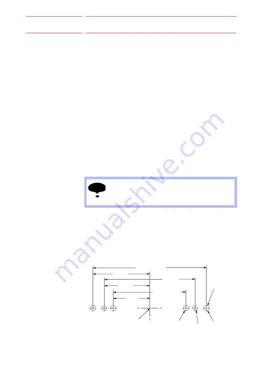
The dowel pins must be installed into the back of the mounting block
before the assembly is mounted onto the faceplate. There are four holes
in the back of the mounting block. See
to determine which
holes to use for your application. If your headstock faceplate does not
have the matching dowel holes, it must be modified per the following
template.
Fig. 4-31: MotoMount Mounting Hole Pattern
NOTE
Notify shipping contractor if there is any shipping damage.
M12 X 1.75
MH95/185 DOWEL
POSITION
250.00 MM +/- 0.015
125 MM
CENTER OF
ROTATION
DIA. 12.00 THRU
FOR DOWEL
200 MM
80 MM
100.0 MM
160.00 MM +/- 0.015
48/101


