Internal cables and compressed air lines
8
-
47
8
Internal cables and compressed air lines
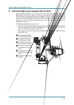
Internal cables (23 wires 11 x 0.75 mm² and 12 x 0.5 mm²) and cables for the external
axes(4 wires x 2.00 mm², 2 wires x 0.75 mm² and 5 wires x 0.20 mm²) and air hoses are
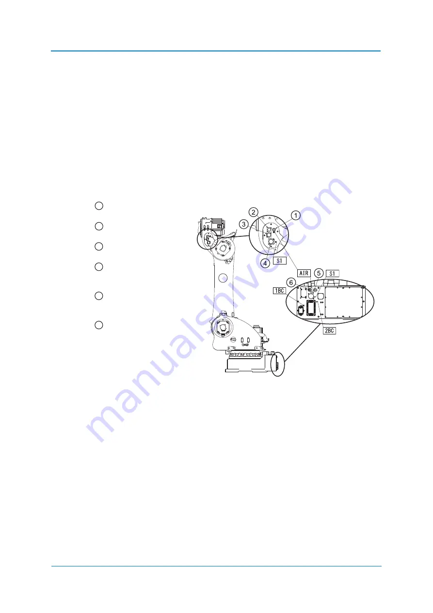
used in order to use peripheral devices (e.g. gripper). They are mounted on the upper arm
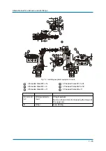
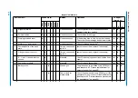
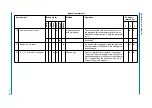
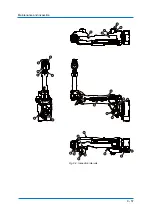
as shown in the following diagram "Connector for internal cables and compressed air lines".
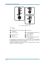
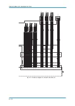
The pins 1 to 23 (1 to 16) are assigned as shown in the following figure. Wiring must be
performed by the user.
The following requirements must be met:
•
The current-carrying capacity per single conductor (cross-section 2.00 mm², 0.75 mm²,
0.50 mm² and 0.20 mm²) must not exceed 16.1 A or less at 2.00 mm
²
, 5.0 A at 0.75
mm², 3.5 A at 0.50 mm² and 2.3 A at 0.2 mm² .
•
The air pressure for the air hose must not exceed 600 kPA (the inner diameter of the air
hose is Ø 8 mm).
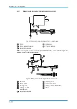
Exhaust port (air flow)
with locking cap (PT3/8)
Connector for the exter-
nal axis (power cable ).
Connector for the exter-
nal axis (encoder cable ).
Connector for the internal
wiring harness on casing
cover.
Connector for the internal
wiring harness on casing
cover.
Air inlet with locking cap
(PT3/8)
1
2
3
4
5
6

