INSTALLATION
ArcWorld IV-6200 XHD DR2C System Manual
4-8
MOTO
MAN
3. Fasten the robot common base to the positioner beam using hardware
removed in Step 1.
WARNING!
Metal bands are under tension and, when cut, may cause injury. Be
cautious when cutting the metal bands.
4. Cut bands securing the floor cover plate and remove it from the robot
common base. The cover plate will be replaced after cables have been routed
beneath the common base and programming platform.
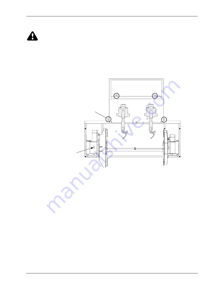
5. Using a M36 socket to turn each leveling bolt, level the robot common base.
Figure 4-8 Robot Common Base Leveling Points
6. Insert a 1/2-inch concrete drill bit through the center of each leveling bolt
(see Figure 4-3) and drill holes (at least four inches deep into concrete) for
anchor bolts.
7. Vacuum concrete dust from holes.
8. Prepare a 1/2-inch anchor (factory-supplied) with accompanying washer and
nut (see Figure 4-4) for each anchor location.
9. Using a hammer, drive an anchor into each drilled hole until the washer stops
at the leveling bolt.
10. Using a 3/4-inch wrench, tighten the nut (clockwise) on each anchor until
tight.
11. Carefully remove protective plastic wrapping from robots and torches.
12. Inspect robots, torches, and positioner for shipping damage.
NOTE:
If damage is found, notify shipper immediately.
POSITIONER
SHIPPING/LAGGING/
LEVELING BOLT
LOCATIONS


