background image

FS100

vi

HW1480758

HW1480758

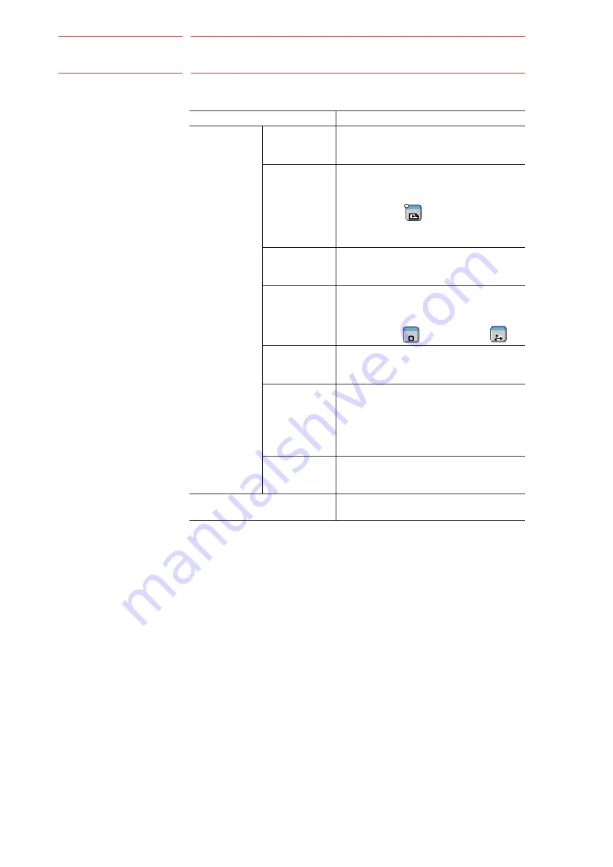
Descriptions of the programming pendant keys, buttons, displays and 
keyboard of the PC are shown as follows: 

Description of the Operation Procedure

In the explanation of the operation procedure, the expression "Select • • • " 
means that the Cursor is moved to the object item and the SELECT key is 
pressed, or that the item is directly selected by touching the screen. 

Registered Trademark

In this manual, names of companies, corporations, or products are 
trademarks, registered trademarks, or brand names for each company or 
corporation. The indications of (R) and TM are omitted. 

Equipment

Manual Designation

Programming 
Pendant

Character Keys The keys which have characters printed on 

them are denoted with [ ].  
ex. [ENTER] 

Symbol Keys

The keys which have a symbol printed on 
them are not denoted with [ ] but depicted 
with a small picture.  

ex. PAGE key 


The Cursor is an exception, and a picture is 
not shown. 

Axis Keys 
Numeric Keys

“Axis Keys” and “Numeric Keys” are generic 
names for the keys for axis operation and 
number input.  

Keys pressed 
simultaneously

When two keys are to be pressed 
simultaneously, the keys are shown with a 
“+” sign between them, 

ex. SHIFTkey 

+ COORD key 


Mode Key

Three kinds of modes that can be selected 
by the mode key are denoted as follows:
REMOTE, PLAY, or TEACH

Button

Three buttons on the upper side of the 
programming pendant are denoted as 
follows:
HOLD button
START button
EMERGENCY STOP button

Displays

The menu displayed in the programming 
pendant is denoted with { }.  
ex. {JOB}

PC Keyboard

The name of the key is denoted
ex. Ctrl key on the keyboard

GO BACK

PAGE

SHIFT

TOOL SEL

COORD

6/20

Summary of Contents for MOTOMAN FS100

Page 1: ...G FUNCTION Upon receipt of the product and prior to initial operation read these instructions thoroughly and retain for future reference MOTOMAN INSTRUCTIONS MOTOMAN INSTRUCTIONS FS100 INSTRUCTIONS FS...

Page 2: ...operating this product The drawings and photos in this manual are representative examples and differences may exist between them and the delivered product YASKAWA may modify this model without notice...

Page 3: ...ARNING Indicates a potentially hazardous situation which if not avoided could result in death or serious injury to personnel CAUTION Indicates a potentially hazardous situation which if not avoided co...

Page 4: ...ot system signal connector CN2 Upon shipment of the FS100 this signal is connected by a jumper cable in the dummy connector To use the signal make sure to prepare a new connector and then input it If...

Page 5: ...n Always press an emergency stop button immediately if there are problems CAUTION Perform the following inspection procedures prior to conducting manipulator teaching If problems are found repair them...

Page 6: ...are denoted with ex ENTER Symbol Keys The keys which have a symbol printed on them are not denoted with but depicted with a small picture ex PAGE key The Cursor is an exception and a picture is not s...

Page 7: ...ing Function 2 1 2 1 Data to be Logged 2 1 2 2 Data to be Logged 2 2 3 Operation 3 1 3 1 List of Log 3 1 3 2 Display of detailed log 3 3 3 3 Update of Logging Information 3 6 3 4 Delete of Logging Inf...

Page 8: ...is function stores the history log of operation on the controller and data edit in chronological order and shows them on the display This function also allows users to obtain the log and enables the l...

Page 9: ...e of manipulator home position Login logoff only when the password protection function is used Edit system Job Addition of instructions Change of conditions in instructions Delete of instructions CUT...

Page 10: ...2 HW1480758 HW1480758 2 2 Data to be Logged The following shows the number of logging records for each data Operation system 100 pieces Edit system 200 pieces If those numbers are exceeded the old da...

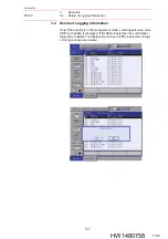
Page 11: ...t of Log 3 1 HW1480758 HW1480758 3 Operation 3 1 List of Log The list of log can be referred by using the following procedure Main Menu SYSTEM INFO LOGDATA When LOGDATA is selected the logging informa...

Page 12: ...n be listed by types operation edit system When DISPLAY is selected from the pull down menu ALL OPERATION and EDITING appears and only the log for the selected type is shown Only the operation system...

Page 13: ...pressed details of the selected log are shown When RETURN is touched at the lower part of the window or CANCEL key is pressed the list window is returned Items that appear in the detailed log window a...

Page 14: ...b selection Series Job name Safety fence OPEN Series Job name Line number Current value Master job call Series Job name File initialization File name File load normal termination File name File save n...

Page 15: ...tion Process end position JOB edit UNDO Series Job name JOB edit REDO Series Job name JOB edit header Numeric Job name Element number Value before edit Value after edit Character string Job name Eleme...

Page 16: ...ion dialog box The log was added Update the display If Yes is selected the log data is obtained again and the display is updated If No is selected the display is not updated but the same dialog box is...

Page 17: ...3 4 Delete of Logging Information Only if the security is in the management mode selecting pull down menu DATA CLEAR is displayed If CLEAR is selected the confirmation dialog box Initialize is display...

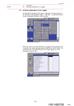
Page 18: ...btaining unnecessary logs can be prohibited Selecting Main Menu SETUP LOGDATA COND shows the logging information setting window When the cursor is moved to the item to be logged and the SELECT key is...

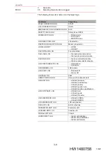
Page 19: ...ion FILE SAVE LOG File save normal termination File save abnormal termination JOB CREATE DELETE LOG JOB creation JOB delete JOB RENAME LOG JOB rename JOB SHIFT LOG Parallel shift Mirror shift JOB PAM...

Page 20: ...inted in Japan October 2011 11 10 C Specifications are subject to change without notice for ongoing product modifications and improvements YASKAWA ELECTRIC CORPORATION FS100 OPTIONS INSTRUCTIONS FOR L...

Reviews: