6
Disassembly and Reassembly of the Speed Reducer
6.6
Disassembly and Reassembly of the T-Axis Speed Reducer
6-18
HW1484673
HW1484673
6.6
Disassembly and Reassembly of the T-Axis Speed
Reducer
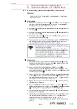
• Refer to
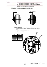
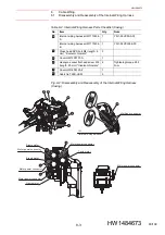
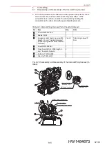
fig. 6-6(a) “Disassembly and Reassembly of the T-Axis
Disassembly
1. When removing the speed reducer
, turn OFF the power supply of
the YRC1000 with the flange surface of the tip of the manipulator
pointing up to keep grease from coming out.
2. Unscrew the hexagon socket head cap screws
, and then remove
the flange
.
3. Unscrew the hexagon socket head cap screws
, and then remove
the speed reducer
.
4. Remove the fine U-nut
, and then remove the washer, gear, and
shim from the speed reducer
.
5. Apply gasket remover (recommended spare parts: LOCTITE 7200) to
the sealing bond left on the flange and wrist, and then leave it for
approximately 15 minutes till it is soft enough to remove.
Reassembly
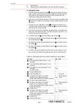
1. Mount the washer, gear, and shim on the speed reducer
. (The
washer is provided with the speed reducer
.) (Refer to
“Adjustment of T-Axis Gear Part Shim”
2. Apply LOCTITE 243 to the thread part of the fine U-nut
,
and then tighten it with the tightening torque shown in
Axis Speed Reducer Parts Checklist”
. (The fine U-nut
is provided
with the speed reducer
.)
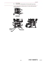
3. Apply LOCTITE 518 to the contact surface of the wrist and the speed
reducer
, and then mount the speed reducer
on the wrist. For
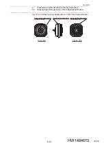
the place to apply sealing bond, refer to
Sealing Bond on the T-Axis Speed Reducer”
4. Tighten the hexagon socket head cap screws
with the tightening
torque shown in
.
5. Apply LOCTITE 518 to the contact surface of the flange
and the
speed reducer
, and then mount the flange
on the speed reducer
. For the place to apply sealing bond, refer to
.
6. Tighten the hexagon socket head cap screws
with the tightening
torque shown in
.
7. Replenish grease (Molywhite RE No.00) from the grease inlet. Mount
the hexagon socket head plugs at grease inlets and the grease
exhaust ports after the replenishment of grease. (Refer to
chapter 4.1.2 “Grease Exchange Procedure”
(B-axis, T-axis, and
gears).)
NOTE
• The gasket remover adhered to the outside of the manipu-
lator may remove the paint.
To prevent the paint from being removed by the gasket
remover, apply masking tape, etc. to the immediate vicinity
of the exterior part where gasket remover is applied.
• When removing the sealing bond, use a resin spatula, etc.
to prevent the flange part from being damaged.
1
4
3
2
1
5
1
1
1
5
5
1
1
1
2
3
1
3
1
4
73/109


