9.2 Notes on Maintenance Procedures
9-14
9.2.6
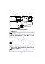
Grease Replenishment for B-, T-axes Speed
Reducers
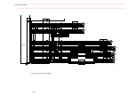
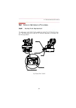
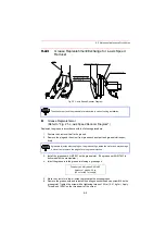
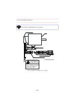
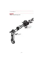
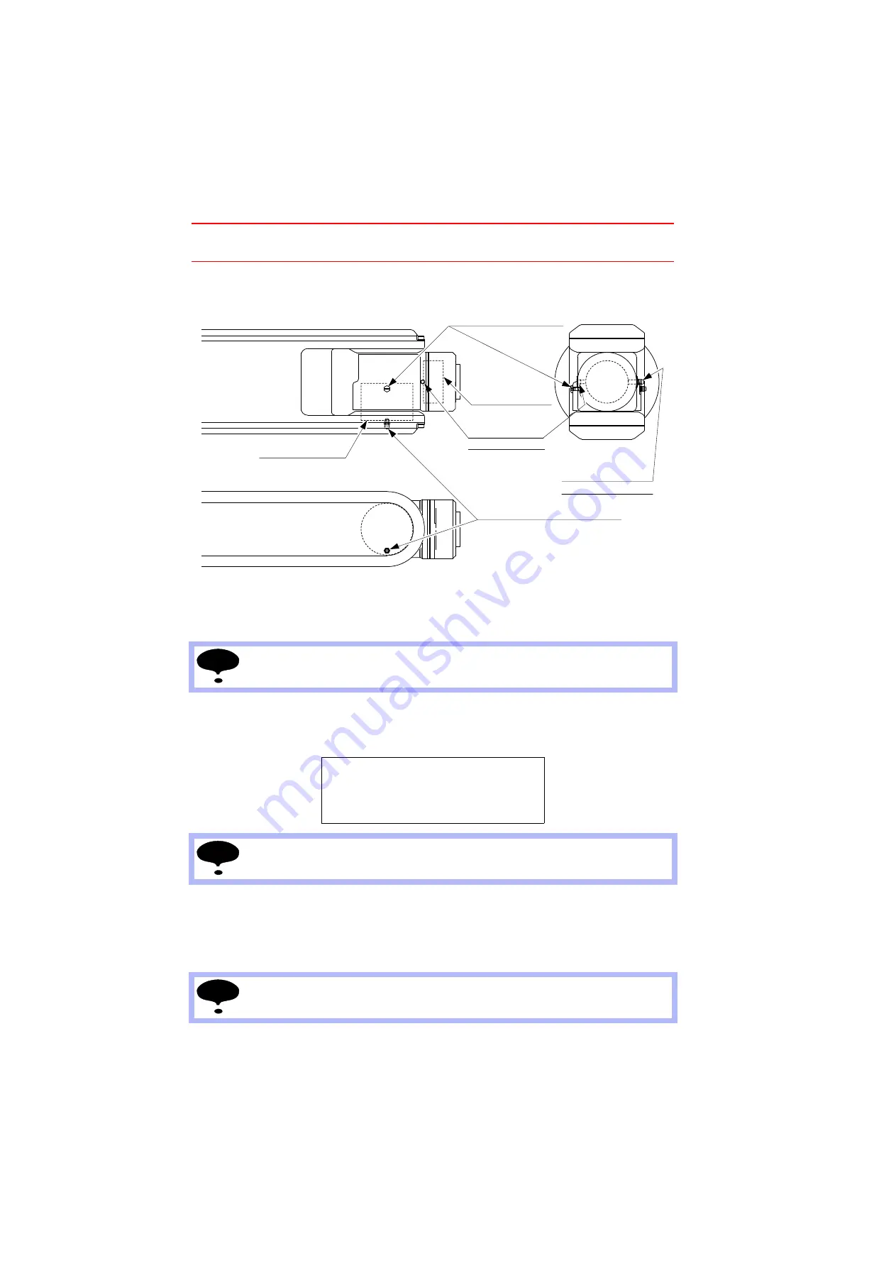
Fig. 28 B-, T-axes Speed Reducers Diagram
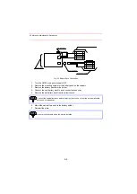
1. Remove the plug on the exhaust port for B-axis or the hexagon socket set screw on the
exhaust port for T-axis.
2. Remove the hexagon socket head cap screw on the grease inlet and install the grease
zerk A-MT6X1.
3. Inject the grease into the grease inlet using a grease gun.
4. Reinstall the plug on the exhaust port for B-axis or the hexagon socket set screw on
the exhaust port for T-axis. Apply Three Bond 1206C on the thread parts.
5. Remove the grease zerk on the grease inlet and reinstall the hexagon socket head cap
screw. Tighten the screw with a tightening torque of 5 N·m (0.51 kgf·m). Apply Three
Bond 1206C on the thread part.
Remove the cover for the B-axis speed reducer.
Grease type: Harmonic grease SK-1A
Amount of grease:
For B-axis: 10 cc (20 cc for the 1st supply)
For T-axis: 5 cc (10 cc for the 1st supply)
The exhaust port is used for air flow. Do not inject excessive grease into the grease inlet.
Mount the cover for the B-axis speed reducer. (Refer to " 9.2.9 Notes for Maintenance.")
B-axis speed reducer
T-axis speed reducer
Gease inlet (for B-axis)
Gease inlet (for T-axis)
(Hexagon socket
set screw M6)
Exhaust port (for T-axis)
Exhaust port (for B-axis)
(Plug LP-M5)
(Hexagon socket head
cap screw M6)
(Hexagon socket head cap screw M6)
NOTE
NOTE
NOTE

