5
Basic Specifications
5.2 Part Names and Working Axes
5-2
156226-1CD
HW0484971
MA1900
5.2
Part Names and Working Axes
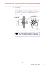
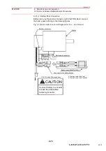
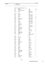
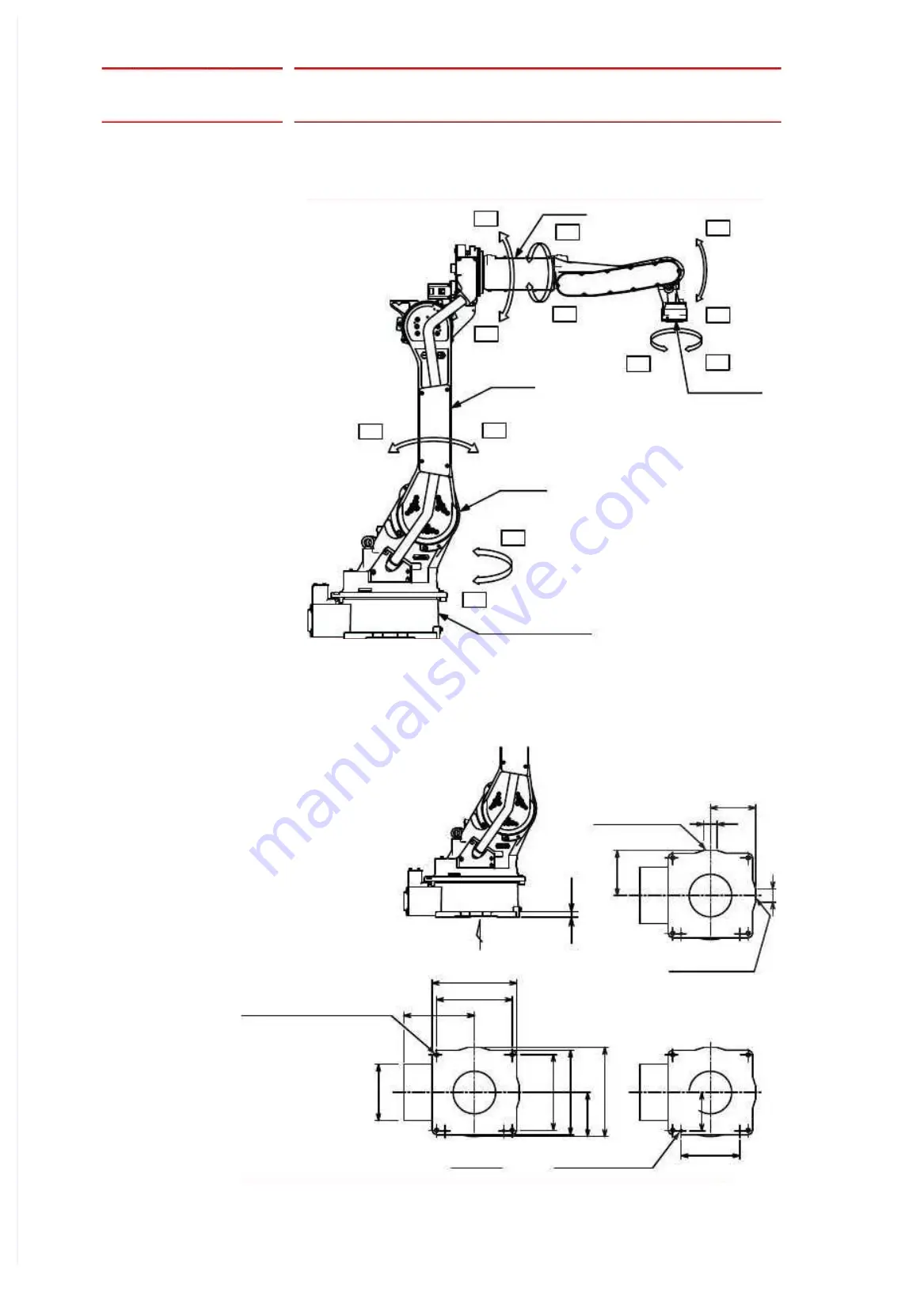
Fig. 5-1: Part Names and Working Axes
5.3
Manipulator Base Dimensions
Fig. 5-2: Manipulator Base Dimensions
Wrist flange
T+
T-
B-
B+
R+
R-
U-
U+
L-
L+
S-
S+
U-arm
L-arm
Manipulator base
S-head
3
9
5
.
5
1
9
5
.
5
6
0
±
0.1
60
200
2
0
0
±
0
.
1
±
0
.
1
260
1
7
0
±
0.1
3
3
5
3
7
5
2
5
0
313
335
375
2
5
A
View A
18 dia. (4 holes)
(For fixing the manipulator)
Units: mm
Fitting surface
Fitting surface
12
dia. hole
(2 holes)
+0.018
0
26/79


