5-2
171469-1CD
HW0485750
MH5
5 Basic Specifications
5.2 Part Names and Working Axes
5.2
Part Names and Working Axes
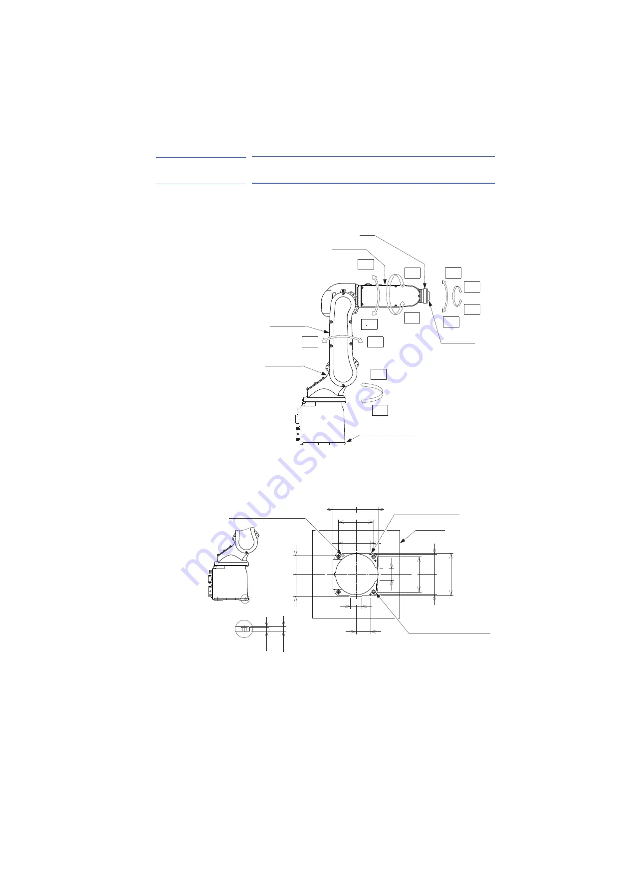
Fig. 5-1: Part Names and Working Axes
5.3
Baseplate Dimensions
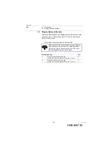
Fig. 5-2: Manipulator Base Dimensions
Wrist
Upper arm
(U-arm)
Wrist flange
Manipulator base
Lower arm
(L-arm)
Rotary head
T-
T+
B+
B-
R-
R+
U-
U+
L-
L+
S-
S+
12
10
194
105
±
0.05
100
92
±
0.1
92
±
0.1
66
±
0.1
±
0.1
85
±
0.05
100
±
0.1
66
±
0.1
60
12 dia. hole for mounting (4 holes)
6 dia. (Standard hole)
(2 holes)
Baseplate
12 dia. (Standard hole)
160
50
50
+0.012
0
+0.018
0
160
33 of 74


