background image

     Programming, Operation, and Maintenance Safety
  

x

163471-1CD

HW1481050

MH50/MH50-35/MH80/
MS80 Zeroing

Programming, Operation, and Maintenance Safety

All operators, programmers, maintenance personnel, supervisors, and 
anyone working near the system must become familiar with the operation 
of this equipment. Improper operation can result in personal injury and/or 
damage to the equipment. Only trained personnel familiar with the 
operation, manuals, electrical design, and equipment interconnections of 
this equipment should be permitted to program, or maintain the system. 
All personnel involved with the operation of the equipment must 
understand potential dangers of operation.

• Inspect the equipment to be sure no potentially hazardous conditions 

exist. Be sure the area is clean and free of water, oil, debris, etc.

• Be sure that all safeguards are in place. Check all safety equipment 

for proper operation. Repair or replace any non-functioning safety 
equipment immediately.

• Check the E-Stop button on the operator station for proper operation 

before programming. The equipment must be placed in Emergency 
Stop (E-Stop) mode whenever it is not in use.

• Back up all programs and jobs onto suitable media before program 

changes are made. To avoid loss of information, programs, or jobs, a 
backup must always be made before any service procedures are 
done and before any changes are made to options, accessories, or 
equipment.

• Any modifications to the controller unit can cause severe personal 

injury or death, as well as damage to the robot! Do not make any 
modifications to the controller unit. Making any changes without the 
written permission from YASKAWA will void the warranty.

• Some operations require standard passwords and some require 

special passwords. 

• The equipment allows modifications of the software for maximum 

performance. Care must be taken when making these modifications. 
All modifications made to the software will change the way the 
equipment operates and can cause severe personal injury or death, 
as well as damage parts of the system. Double check all 
modifications under every mode of operation to ensure that the 
changes have not created hazards or dangerous situations.

• This equipment has multiple sources of electrical supply. Electrical 

interconnections are made between the controller and other 
equipment. Disconnect and lockout/tagout all electrical circuits 
before making any modifications or connections.

• Do not perform any maintenance procedures before reading and 

understanding the proper procedures in the appropriate manual.

• Use proper replacement parts.

• Improper connections can damage the equipment. All connections 

must be made within the standard voltage and current ratings of the 
equipment.

10 of 51

Summary of Contents for MOTOMAN-MH50

Page 1: ...NG SPECIFICATION Upon receipt of the product and prior to initial operation read these instructions thoroughly and retain for future reference MOTOMAN INSTRUCTIONS MOTOMAN MH50 INSTRUCTIONS MOTOMAN MH...

Page 2: ...al is copyrighted property of YASKAWA and may not be sold or redistributed in any way You are welcome to copy this document to your computer or mobile device for easy access but you may not copy the P...

Page 3: ...e reading this manual CAUTION Some drawings in this manual are shown with the protective covers or shields removed for clarity Be sure all covers and shields are replaced before operating this product...

Page 4: ...r is responsible for providing adequately trained personnel to operate program and maintain the equipment NEVER ALLOW UNTRAINED PERSONNEL TO OPERATE PROGRAM OR REPAIR THE EQUIPMENT We recommend approv...

Page 5: ...to personnel CAUTION Indicates a potentially hazardous situation which if not avoided could result in minor or moderate injury to personnel and damage to equipment It may also be used to alert agains...

Page 6: ...mum envelope of the manipulator Be sure to use a lockout device to the safeguarding when going inside Also display the sign that the operation is being performed inside the safeguarding and make sure...

Page 7: ...gistered trademarks or brand names for each company or corporation The indications of R and TM are omitted CAUTION Perform the following inspection procedures prior to conducting manipulator teaching...

Page 8: ...ollow the warnings on the labels Also an identification label with important information is placed on the body of the manipulator Prior to operating the manipulator confirm the contents Figure 3 Warni...

Page 9: ...whenever it is not in use In accordance with ANSI RIA R15 06 2012 section 4 2 5 Sources of Energy use lockout tagout procedures during equipment maintenance Refer also to Section 1910 147 29CFR Part...

Page 10: ...s or jobs a backup must always be made before any service procedures are done and before any changes are made to options accessories or equipment Any modifications to the controller unit can cause sev...

Page 11: ...rained qualified personnel Summary of Warning Information This manual is provided to help users establish safe conditions for operating the equipment Specific considerations and precautions are also d...

Page 12: ...o 36 hours for a response to your inquiry Please have the following information ready before you call Customer Support techsupport motoman com NOTE Please use e mail for routine inquiries only If you...

Page 13: ...n of the Zeroing Device Using the USB Connector 1 3 1 2 2 Operational Procedure and Cautions 1 4 1 2 2 1 Before the Zeroing Operation 1 4 1 2 2 2 Connection of the Zeroing Devices 1 4 1 2 2 3 Zeroing...

Page 14: ...rmed at the normal operation However zeroing operation needs to be performed to restore the home position since the home position data disappear when you perform the following operations or the follow...

Page 15: ...le 1 1 Components for Zeroing Device Using CF Card Slot Component Type Qty Manufacturer Sensor HW0381863 A 1 YASKAWA Electric Corporation Amplifier HW0381864 A 1 YASKAWA Electric Corporation Lead wire...

Page 16: ...1863 A 1 YASKAWA Electric Corporation Amplifier HW0381864 A 1 YASKAWA Electric Corporation Lead wire HW0470652 A 1 YASKAWA Electric Corporation Communication cable C232N 915 1 YASKAWA Electric Corpora...

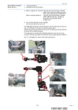
Page 17: ...munication interface REX CF60 into the CF card slot of the programming pendant When using the USB slot Insert the communication interface REX USB60F into the USB slot of the programming pendant Fig 1...

Page 18: ...C232N 915 3 Connect the lead wire to the amplifier Do not connect the sensor yet The installation locations of the zeroing sensors for each axis are shown in Fig 1 4 Installation Locations of the Zero...

Page 19: ...st if they are found S axis NOTE Be sure to remove the cover If the zeroing operation is performed with the cover on the sensor may be damaged NOTE The plug cover and cover mounting screws are small p...

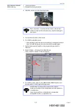
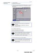
Page 20: ...h on the programming pendant to TEACH 8 Select Robot Zeroing from Main Menu Then select S S axis on the touch panel 9 Turn ON the servo power by the SERVO ON READY button and Enable switch on the prog...

Page 21: ...the message in the pop up window and the manipulator starts automatically NOTE Confirm that no persons are present in the P point maximum envelope of the manipulator and the operator is in a safe pla...

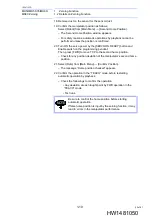
Page 22: ...install the plug and cover onto the manipulator NOTE Be sure to turn OFF the servo power to approach the manipulator Injury may result from unintentional or unexpected manipulator motion NOTE After th...

Page 23: ...witch on the programming pendant Then press FWD to move TCP to the second home position Check for any position deviation of the manipulator s second home position 21 Select Data from Main Menu Confirm...

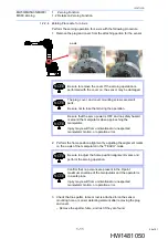
Page 24: ...ust if they are found L axis NOTE Be sure to remove the cover If the zeroing operation is performed with the cover on the sensor may be damaged NOTE The plug cover and cover mounting screws are small...

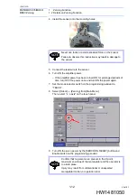
Page 25: ...ch on the programming pendant to TEACH 8 Select Robot Zeroing from Main Menu Then select L L axis on the touch panel 9 Turn ON the servo power by the SERVO ON READY button and Enable switch on the pro...

Page 26: ...the message in the pop up window and the manipulator starts automatically NOTE Confirm that no persons are present in the P point maximum envelope of the manipulator and the operator is in a safe pla...

Page 27: ...install the plug and cover onto the manipulator NOTE Be sure to turn OFF the servo power to approach the manipulator Injury may result from unintentional or unexpected manipulator motion NOTE After th...

Page 28: ...witch on the programming pendant Then press FWD to move TCP to the second home position Check for any position deviation of the manipulator s second home position 21 Select Data from Main Menu Confirm...

Page 29: ...they are found U axis NOTE Be sure to remove the cover If the zeroing operation is performed with the cover on the sensor may be damaged NOTE The plug cover and cover mounting screws are small parts b...

Page 30: ...ch on the programming pendant to TEACH 8 Select Robot Zeroing from Main Menu Then select U U axis on the touch panel 9 Turn ON the servo power by the SERVO ON READY button and Enable switch on the pro...

Page 31: ...the message in the pop up window and the manipulator starts automatically NOTE Confirm that no persons are present in the P point maximum envelope of the manipulator and the operator is in a safe pla...

Page 32: ...install the plug and cover onto the manipulator NOTE Be sure to turn OFF the servo power to approach the manipulator Injury may result from unintentional or unexpected manipulator motion NOTE After th...

Page 33: ...witch on the programming pendant Then press FWD to move TCP to the second home position Check for any position deviation of the manipulator s second home position 21 Select Data from Main Menu Confirm...

Page 34: ...th the cover on the sensor may be damaged NOTE The plug cover and cover mounting screws are small parts Be sure not to lose them during the operation NOTE Be sure that the servo power is OFF and no sa...

Page 35: ...the sensor onto the mounting holes 5 Connect the lead wire to the sensor 6 Turn ON the amplifier power If the amplifier power has been turned ON for prolonged periods of time turn OFF the power once a...

Page 36: ...s automatically NOTE Confirm that no persons are present in the P point maximum envelope of the manipulator and the operator is in a safe place Injury may result from unintentional or unexpected manip...

Page 37: ...install the plug and cover onto the manipulator NOTE Be sure to turn OFF the servo power to approach the manipulator Injury may result from unintentional or unexpected manipulator motion NOTE After th...

Page 38: ...witch on the programming pendant Then press FWD to move TCP to the second home position Check for any position deviation of the manipulator s second home position 21 Select Data from Main Menu Confirm...

Page 39: ...ust if they are found B axis NOTE Be sure to remove the cover If the zeroing operation is performed with the cover on the sensor may be damaged NOTE The plug cover and cover mounting screws are small...

Page 40: ...ch on the programming pendant to TEACH 8 Select Robot Zeroing from Main Menu Then select B B axis on the touch panel 9 Turn ON the servo power by the SERVO ON READY button and Enable switch on the pro...

Page 41: ...the message in the pop up window and the manipulator starts automatically NOTE Confirm that no persons are present in the P point maximum envelope of the manipulator and the operator is in a safe pla...

Page 42: ...install the plug and cover onto the manipulator NOTE Be sure to turn OFF the servo power to approach the manipulator Injury may result from unintentional or unexpected manipulator motion NOTE After th...

Page 43: ...tch on the programming pendant Then press FWD to move TCP to the second home position 21 Check for any position deviation of the manipulator s second home position 22 Select Data from Main Menu Confir...

Page 44: ...ust if they are found NOTE Be sure to remove the cover If the zeroing operation is performed with the cover on the sensor may be damaged NOTE The plug cover and cover mounting screws are small parts B...

Page 45: ...ch on the programming pendant to TEACH 8 Select Robot Zeroing from Main Menu Then select T T axis on the touch panel 9 Turn ON the servo power by the SERVO ON READY button and Enable switch on the pro...

Page 46: ...the message in the pop up window and the manipulator starts automatically NOTE Confirm that no persons are present in the P point maximum envelope of the manipulator and the operator is in a safe pla...

Page 47: ...einstall the plug and cover onto the manipulator NOTE Be sure to turn OFF the servo power to approach the manipulator Injury may result from unintentional or unexpected manipulator motion NOTE After t...

Page 48: ...witch on the programming pendant Then press FWD to move TCP to the second home position Check for any position deviation of the manipulator s second home position 21 Select Data from Main Menu Confirm...

Page 49: ...ceeded ErrorCode 55550005 Error in the zeroing processing Possible causes False parameter settings for zeroing speed distance radius and etc false starting point of the zeroing operation and etc Conta...

Page 50: ...the programming pendant Insert the CF Card for the RS 232C into the slot Error RS 232C Communication ErrorCode 55550017 Errors occur during the amplifier communication Contact your nearest YASKAWA rep...

Page 51: ...orporate Avenue No 222 Hubin Road Huangpu District Shanghai 200021 China Phone 86 21 5385 2200 Fax 86 21 5385 3299 YASKAWA Electric Thailand Co Ltd 59 1st 5th Floor Flourish Building Soi Ratchadapisek...

Reviews: