6
Disassembly and Reassembly of Speed Reducer
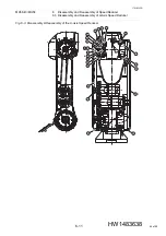
6.2 Disassembly and Reassembly of L-Axis Speed Reducer
6-5
176183-1CD
HW1483638
MH5S
(II)
/MH5F
6. Temporarily tighten the GT-SA bolts
.
7. Apply Harmonic Grease SK-1A on the surface between the teeth of
flex spline
and the circular spline
and insert the circular spline
in the L-arm.
8. Attach the conical spring washers
to the hexagon socket head cap
screws
and tighten them with the tightening torque shown in
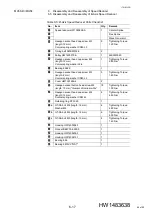
Table 6-2 “L-Axis Speed Reducer Parts Checklist”
9. Apply ThreeBond 1206C to the thread parts of the GT-SA bolts
and
tighten them with the tightening torque shown in
.
10. Insert the bearings
in the wave generator
. Then insert it in the
housing
. (Apply ThreeBond 1206C to the outside and inside walls of
*a and insert it in the housing
and the wave generator
.) (When
replace the speed reducer, replace the bearings
too.)
11. Tighten the GT-SA bolts
with the tightening torque shown in
12. Mount the pulley
on the wave generator
.
13. Attach the conical spring washer to the hexagon socket head cap
screw
and apply LOCTITE 638 to its thread part. Then tighten it
with the tightening torque shown in
14. Apply ThreeBond 1206C to the matching face between the housing
mounted the wave generator
and the circular spline
. Then mount
the housing
and the circular spline
.
15. Put the timing belt on the pulley
.
(Refer to
and Reassembly of L- and U-Axis Timing Belts”
.)
16. Put the internal wiring harness back and mount the cover
. (Refer to
17. Turn ON the DX100/DX200/FS100 power supply.
12
2
1
1
20
4
4
16
3
9
16
9
3
16
6
8
3
7
9
3
1
9
1
8
13
52 of 99


